How to rid complex piping systems of air
I can’t see it, but it’s there.
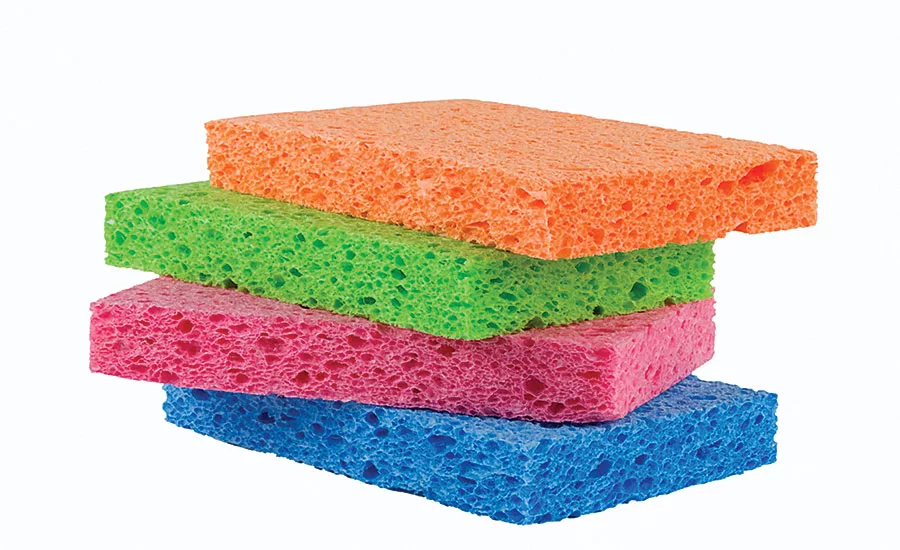
Think of water as a sponge for dissolved gases such as those in the air.
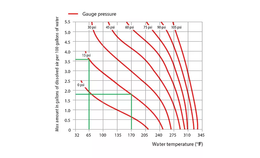
Figure 1.
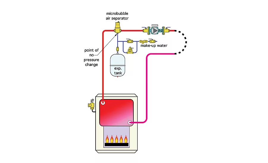
Figure 2.
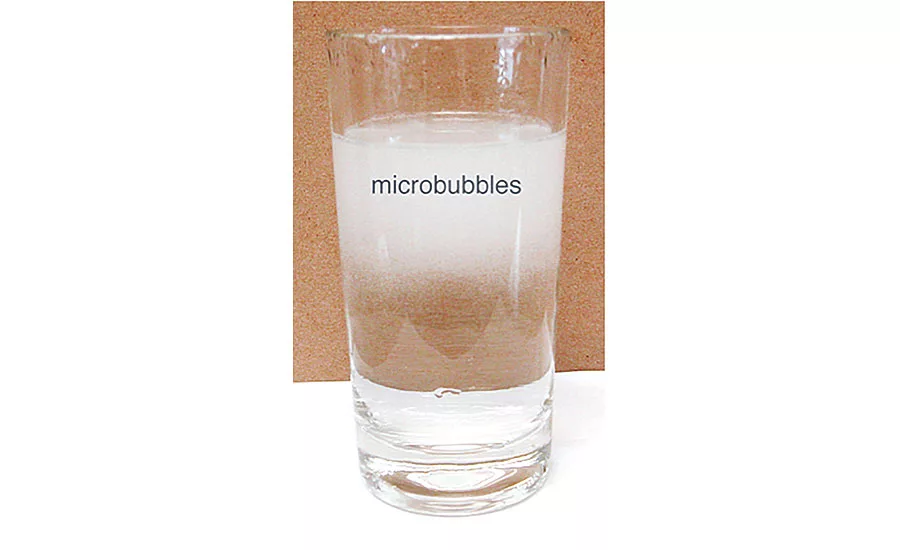
Figure 3. Microbubbles
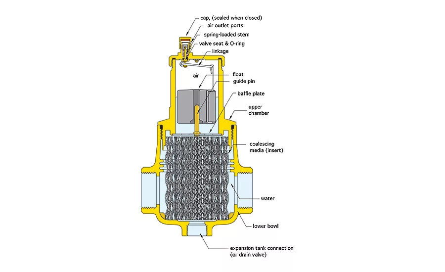
Figure 4.
Air bubbles in water are as common as clouds in the sky or waves on a lake. Most people take them for granted. However, those working with hydronic systems quickly learn that air in their systems is undesirable and seek ways to get rid of it.
My “attitude” on air in hydronic systems has changed over the years. I used to fear situations where air could get trapped in system piping and create problems such as loss of flow, noise and the (justified) complaints that would follow. Part of that fear was based on my inadequate understanding of how air behaves in a hydronic system.
Today, I know that proper system design, including provisions for forced-water purging in combination with residual methods for air elimination, can quickly rid just about any hydronic system of air and keep it that way.
Air in a hydronic system can be categorized into three groups: 1) stationary air pockets, 2) entrained air bubbles and 3) air dissolved with fluid.
Since air is lighter than water it migrates toward the high points of the system. These points are not necessarily just at the top of the system. Stationary air pockets can form at the top of heat emitters such as radiators, even those located low in the building. They also can form in horizontal piping runs that turn downward following a horizontal run. A common example is where a pipe is offset upward to cross over a beam and then dropped back to its previous level.
Stationary air pockets within piping usually can be eliminated through forced-water purging. A stream of water flowing at high velocity through the piping will push air along much like a piston moving through a cylinder. The air is eventually pushed out through an open valve near the end of the circuit.
Forced-water purging is best driven by water pressure from the building’s domestic water supply system (e.g., water-main pressure or pressure from a well pump). The high velocity flow needed also can be created using a swimming pool pump rated for at least 1 hp, and supplied from a large/clean plastic trash barrel filled with water. Don’t count on the flow created by a properly sized hydronic circulator to displace stationary air pockets, especially when that circulator has a mixture of air and water passing through it.
Stationary air pockets within radiators or at the top of components, such as thermal storage tanks and heat exchangers, is best eliminated through a vent. Hardware choices range from manually operated vents to fully automatic float-operated vents. I like manually operated vents on radiators due to their small size and rather infrequent use once the system has been initially purged. Float-type vents are ideal at the top of thermal storage tanks or central air separators.
Along for the ride
Entrained air bubbles are simply bubbles moved along by water flowing through the piping. Experience has shown that piping with average flow velocities as low as 2 ft. per second can entrain air bubbles even in vertical piping with downward flow.
Entrainment can be helpful in dislodging air from remote portions of the system and bringing it back to a central air-separating device. This assumes ample water circulation in the system to provide the conveyor belt. Again, a good forced-water purging driven by a pressure source other than the system’s circulator(s) is the best way to entrain air and eventually route it out of the system.
Present though unseen
Perhaps the least understood form in which air can exist in a hydronic system is as dissolved air. Molecules of the gases that make up air including oxygen (O2) and nitrogen (N2) can exist “in solution” with water molecules (H2O). These molecules cannot be seen, even under a microscope. Although water may appear perfectly clear and free of bubbles, it still can contain a significant quantity of air in solution.
The amount of dissolved air that water can hold depends on the water’s temperature and pressure. At higher temperatures, the ability of water to contain dissolved gases decreases and vice versa. As the pressure of the water increases, so does its ability to hold dissolved gases in solution.
Have you ever popped the cap on a bottle of beer and instantly seen the bubbles forming and rising? It happens because the pressure on the liquid was reduced, which allows some of the carbon dioxide (CO2) molecules that were dissolved in the beer to merge together into tiny bubbles.
Like squeezing a sponge
Think of water as a “sponge” for dissolved gases such as those in air (mostly oxygen and nitrogen). Certain conditions allow that sponge to soak up additional molecules, while other conditions effectively “squeeze” the sponge and thus rid the water of some of these molecules. This “sponge” effect is driven by temperature and pressure.
The contours in Figure 1 show the maximum amount of dissolved air gases contained in water over a range of temperatures and pressures (expressed as a percentage of total volume).
For example, at 15 psi gauge pressure and a temperature of 65° F, up to 3.6% of the molecules in a container of water can be dissolved gases (oxygen, nitrogen and other trace gases).Water in this condition can be thought of as a sponge that has soaked up a significant amount of air molecules.
If the temperature of this water is raised to 170° while the pressure remains constant, its ability to hold dissolved gas is reduced to 1.8% of its volume, half the previous level. This change in air solubility is typical when cold water is first heated to a relatively high temperature in a boiler. The “sponge” has just been squeezed.
As the pressure of the water is reduced, so is its ability to hold dissolved gases in solution. For example, Figure 1 shows that reducing the pressure of 170° water from 15 psi to 0 psi reduces the amount of dissolved gas it can contain from 1.8% to about 0.6% of its volume. This is another way to squeeze the “sponge.”
Ground zero
The best location for capturing air bubbles is where the ability of water to hold dissolved air is lowest. This is where the combination of temperature and
corresponding pressure produce the lowest point on the graph in Figure 1.
The piping arrangement shown in Figure 2 places a central air separator close to the heat source where the water temperature is at or close to its highest value within the system.
The expansion tank is connected to the bottom of the air separator. This establishes the point of no pressure change (PONPC) in the system.
When the circulator is operating, the pressure at this location will not change. It may not be the lowest pressure in the system (based upon the elevation changes in the piping), but the combination of temperature and pressure at this location is likely to produce a point on the graph in Figure 1 that is either the lowest or very close to the lowest point. This is where the molecules of oxygen and nitrogen in the water join together to form very tiny “microbubbles.” This process is called coalescence.
Individually, microbubbles are too small to be seen by the human eye. However, dense collections of microbubbles can make otherwise clear water appear cloudy. A common place to see temporary clouds of microbubbles is in a drinking glass just filled with water from a faucet having an aerator device as seen in Figure 3.
If you watch the glass of water carefully, you will see the cloud of microbubbles slowly rise and disappear from the surface of the water. At that point the water might look air- free, but it’s not. There still are molecules of oxygen and nitrogen mixed in with the water molecules. Fortunately we have modern devices to coax them out of hiding.
Modern air-separating devices contain a mesh-like insert made of engineered polymers or metal. This insert is called a coalescing media. Figure 4 shows the cross section of a modern air separator and the coalescing media insert.
The coalescing media contains thousands of small sharp surfaces throughout its 3-dimensional structure. These surfaces create tiny vortices (e.g., regions of reduced pressure) as water passes by them. The reduced pressure encourages molecules to coalesce into microbubbles. This is the first step toward the goal of capturing this dissolved air and ejecting it from the system.
Microbubbles are very easily entrained by moving fluids. This characteristic makes them more difficult to capture compared to larger bubbles. However, the surfaces of the coalescing media provide shielded vertical pathways along which microbubbles can rise above the active flow stream moving through the separator. Once they are above this region it’s almost “game over.”
The microbubbles merge into larger bubbles that eventually form an air pocket in the upper chamber of the separator. When sufficient air has accumulated, the float in the upper portion of the separator drops down and a small linkage attached to it opens a valve. This allows the accumulated air to be ejected from the system. The pressure difference between the inside of the separator and the surrounding air is what pushes the air out as this valve opens. As the air leaves, the float rises and the valve closes to prevent all but a tiny loss of water. The automatic makeup water subsystem responds by adding a small amount of water to replace the ejected air.
The water stream exiting the air separator and heading into the circuit is said to be in an “unsaturated” state. This means it is capable of absorbing more molecules of oxygen and nitrogen as it passes through the circuit. Thus, whenever the water is moving through the circuit there is an ongoing process whereby air molecules are absorbed into the water stream, conveyed back to the air separator, scrubbed out of the water by the coalescing media, ejected from the system and replaced by equivalent volumes of water. This process can eventually reduce the dissolved air content of the system’s water to less than 0.4%. This small residual air content doesn’t adversely affect system operation.
Pay attention to details
For optimal performance it’s best to keep the flow velocity of water entering an air separator no higher than 4 ft. per second. Placement of the air separator as shown in Figure 2 provides the air separator an excellent “hunting ground” for capturing dissolved air. Be sure to place purging valves near the end of branch circuits so each of these circuits can benefit from a forced-water purging when the system is commissioned. Follow these details and it’s easy to rid even complex piping systems of air and keep them that way.
This article was originally titled “I can’t see it, but it’s there” in the April 2016 print edition of Supply House Times.
Looking for a reprint of this article?
From high-res PDFs to custom plaques, order your copy today!


