Ways to simplify hydronic heating systems
Reducing complexity.
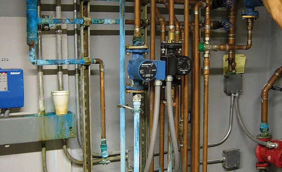
Figure 1. Do you ever feel there are too many pipes, circulators, controls and other gadgets in the hydronic systems you deal with?

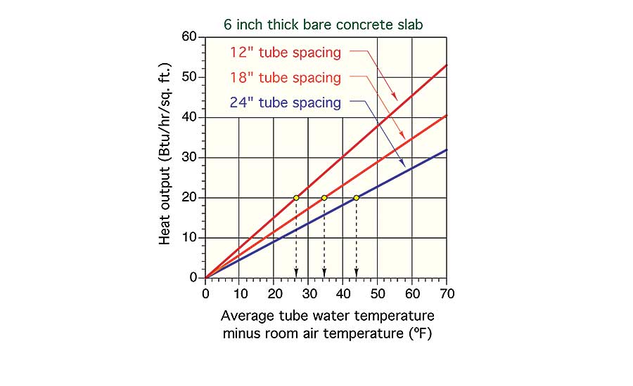
Figure 2. shows if 12-in. tube spacing is used, the average circuit water temperature needs to be about 27° above the room air temperature (e.g. 27+70=97°).
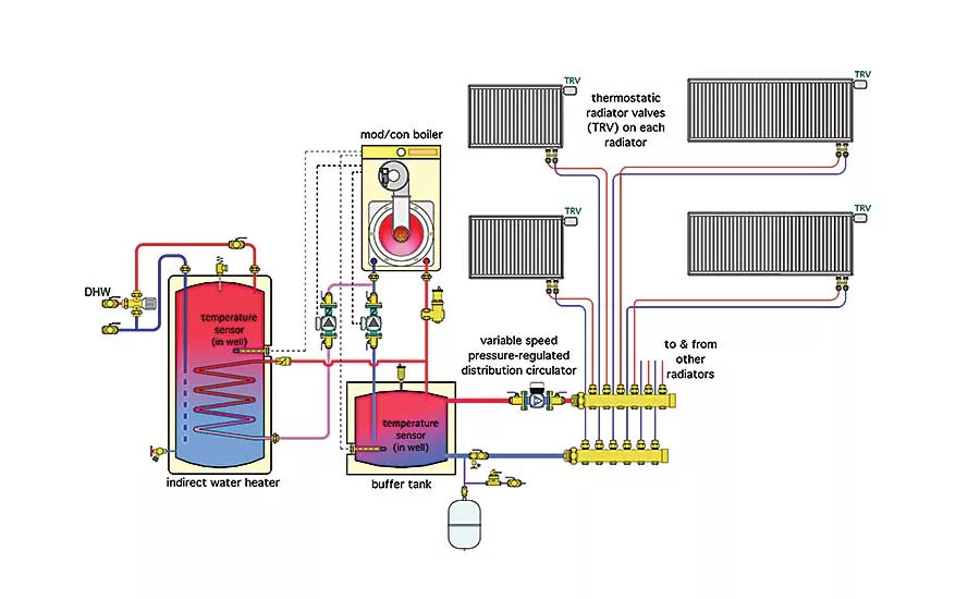
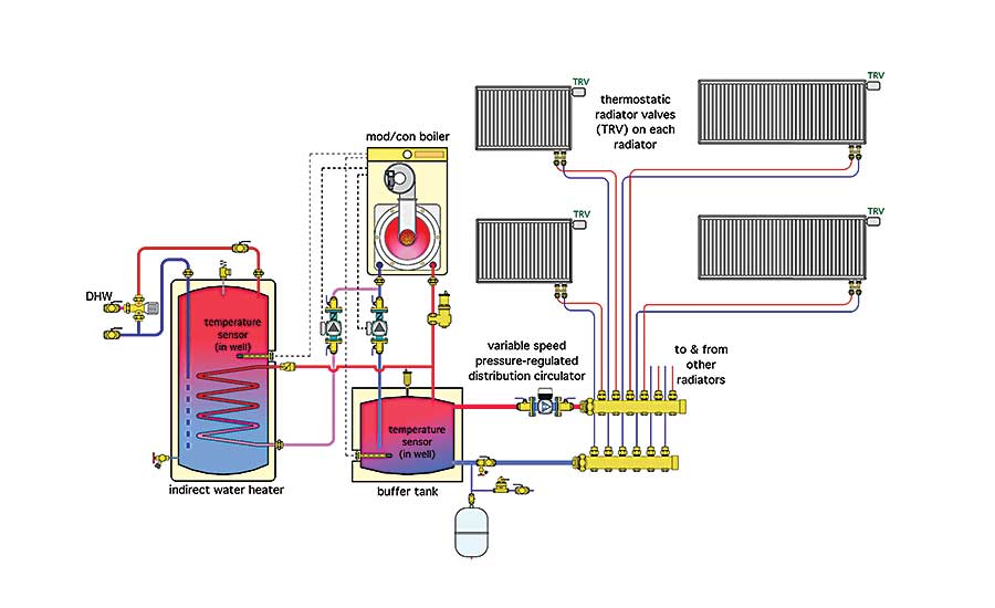
This approach sets the stage for a simple delivery system using a single variable-speed pressure-regulated circulator. An example of such a distribution system is shown in Figure 3.
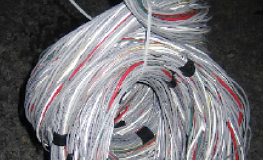
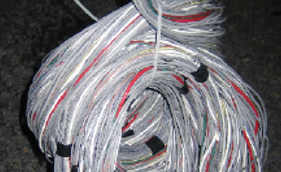
Figure 4. By the time all the transformers, valve actuators, relay centers and thermostats are connected, you may have installed a couple miles of thermostat cable
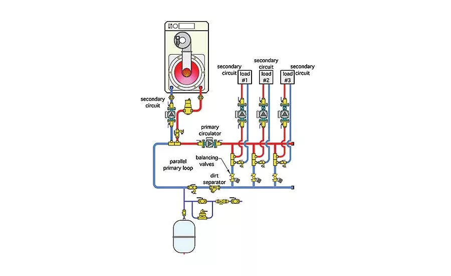
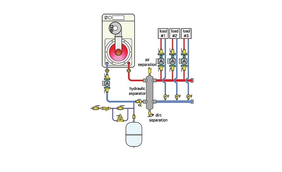
Figure 5. Figures 5 and 6 contrast two approaches for achieving hydraulic separation of all circulators and equal supply water temperature to each load.
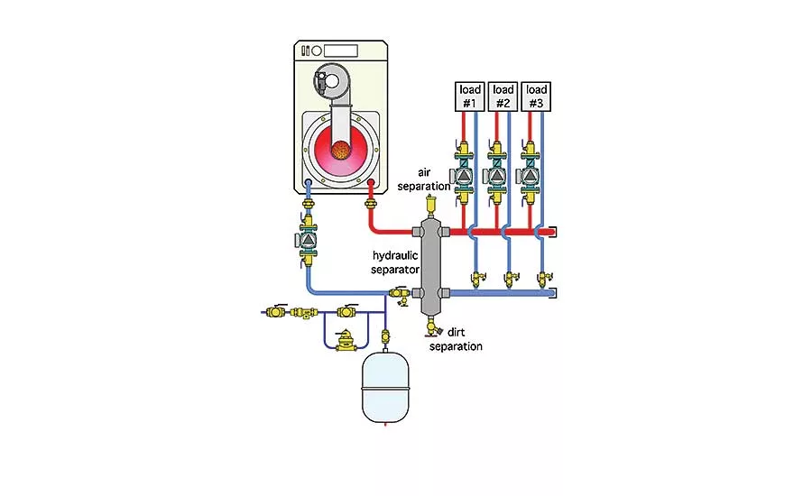
Figure 6. Figures 5 and 6 contrast two approaches for achieving hydraulic separation of all circulators and equal supply water temperature to each load.
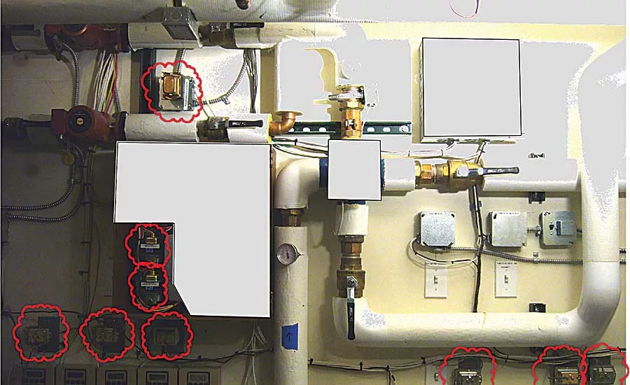
Ever been in a mechanical room where there’s a half-dozen or more transformers mounted on 4-by-4 J-boxes and buzzing away 24/7? Figure 7 shows an example of such a situation.
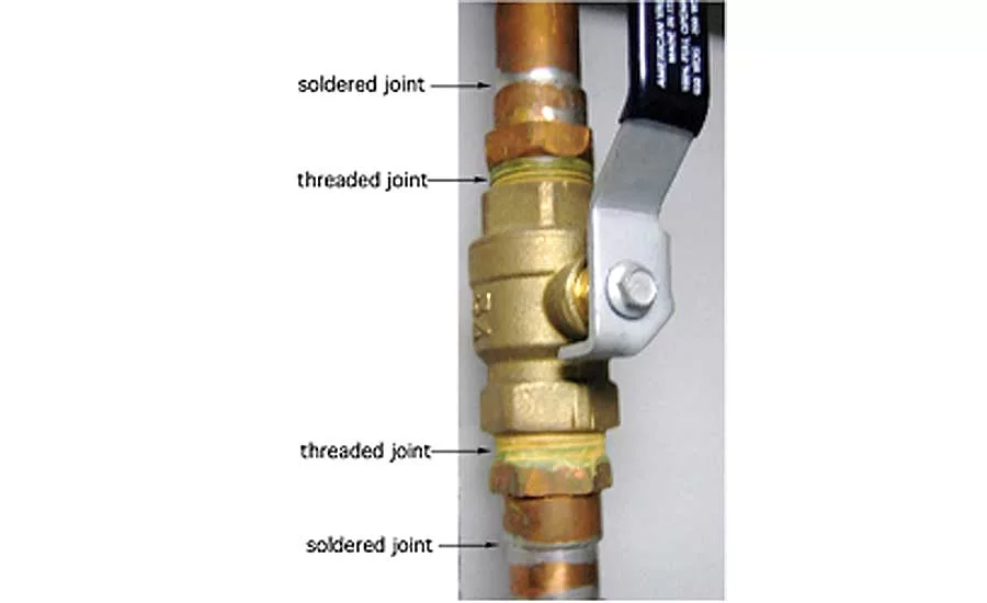
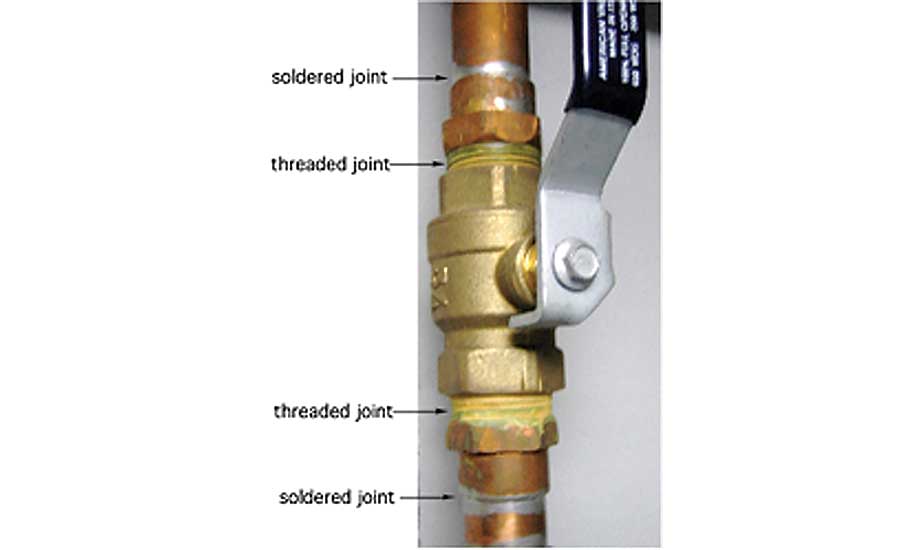
Figure 8. A 2014 estimating manual puts the installed cost of a 1-in. copper x male adapter fitting at $12.26. That adds almost $25 to the cost of installing a 1-in. valve you might have nonchalantly purchased with FPT connections.
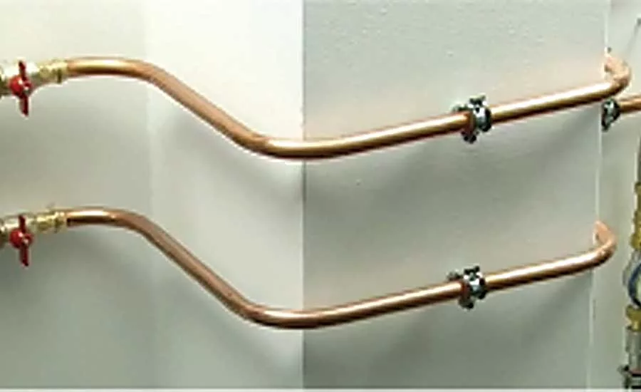
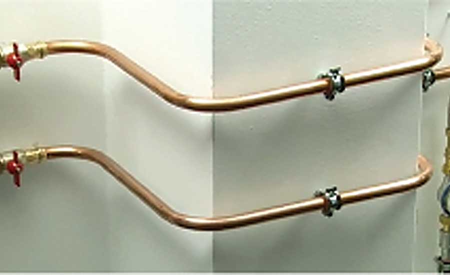
You might also want to consider buying a quality tube bender and fabricating bends in tubing rather than installing elbows, as shown in Figure 9.
Do you ever feel there are too many pipes, circulators, controls and other gadgets in the hydronic systems you deal with?
That may be an odd question for an audience that sells this hardware, but it is nonetheless one that deserves thought, especially if you expect the North American hydronics industry to grow.
Why is it that many well-organized two-dimensional schematics — systems that look so good on paper — often turn into a tangled array of hardware when installed?
Many of us have seen prize-winning hydronic systems displayed in trade journals and other publications over the years. Most of these systems are one-up installations. With proper design, documentation and maintenance, they can serve their owners well. Take away any of these requisites and you have a very expensive collection of hardware that nobody seems to understand or is willing to service.
The latter scenario is a serious issue. The last thing our industry needs is for the average consumer to think hydronic heating has to be complex or that hydronic systems that go beyond a boiler, a circulator and a series loop of fin-tube baseboard cannot be easily maintained by a reasonably competent service tech.
To help avoid such situations it’s prudent to consider ways of simplifying residential hydronic systems. The goal is to trim away at design concepts as well as hardware that in many cases don’t need to be included in the system for it to deliver efficient operation and superior comfort. Here are a few things for you to consider.
Simplifying multi-temperature systems: A common situation in planning radiant panel heating systems is the need for multiple supply water temperatures. An example would be floor heating in a basement slab combined with tube-and-plate floor heating on the main living level of a house.
A common approach is to set up a separate mixing assembly for each type of radiant panel construction. Some designers specify separate mixing assemblies for every area with different types of floor covering (e.g., ceramic tile vs. padded carpet). Sometimes a separate mixing assembly also is specified on a floor-level basis even when the water temperature requirements of the panels being supplied are the same.
I’ve designed residential systems with three different mixing assemblies and I’ve seen systems having at least five independent mixing assemblies. Do these systems work? Yes. Is this complexity necessary? Not necessarily.
The following is a procedure that can be used during design to decide if multiple water temperatures are needed:
-
Add up all the circuit supply water temperature calculated for design load conditions.
-
Calculate the average of these supply temperatures.
-
If the supply temperature for a given circuit is more than 10° F above or below this average temperature, identify that circuit.
-
Consider modifying any of these identified circuits through changes in tube spacing to increase or decrease their required supply water temperature at design load conditions. Try to bring that temperature within +/- 10° of the average temperature of all circuits. Remember to calculate a new average water temperature each time a circuit supply water temperature changes. In basements, consider tube spacings of up to 18 in., or even 24 in., if the basement is infrequently occupied and floor surface temperature variations are not deemed to be a problem.
For example, suppose you’re planning tubing for a bare concrete slab and need 20 Btu/h/ft2 of heat output at design load conditions. The space is to be maintained at 70° under these conditions. Figure 2 (on the following page) shows if 12-in. tube spacing is used, the average circuit water temperature needs to be about 27° above the room air temperature (e.g. 27+70=97°).
Assume the same building has a gypsum thin slab with embedded tubing for heating the upper floor and at design load those circuits need 115° average water temperature.
Increasing the tube spacing in the concrete slab portion of the system to 18 in. increases the average water temperature to about 104°. Assuming a nominal 20° circuit temperature drop, the supply temperatures for these circuits would be about 97+20/2=107° and 104+20/2=114°, respectively. These supply temperatures are within 10° of each other and thus could very likely be supplied from the same system without using separate mixing hardware. In this case, the controls could be set to produce a supply temperature midway between these two values (around 110°).
In this situation it’s better to decrease the tube spacing on the higher temperature circuits and thus bring the average system water temperature down to promote efficiency gains at the heat source. This is especially true for systems using mod/con boilers, geothermal heat pumps or solar collectors as heat sources. When a conventional (non-condensing) boiler is used, the changes in boiler efficiency likely are to be minimal and the cost savings are largely derived by not installing multiple mixing assemblies.
If variations in tube spacing aren’t enough, discuss the possibility of different finish flooring with the client before giving up on use of a single supply temperature.
I’ve found it possible to combine slab-on-grade systems with both thin slabs and even underfloor tube and plate systems in certain circumstances. Eliminating the need for multiple mixing assemblies in these situations can reduce installation cost by hundreds of dollars.
When a single supply water temperature is possible, consider zoning manifolds using zone valves or individual circuits using valve actuators. Another possibility is to mix in nonelectric thermostatic valves for zone control. This approach sets the stage for a simple delivery system using a single variable-speed pressure-regulated circulator. An example of such a distribution system is shown in Figure 3 on the previous page.
Fewer zones: The ability to divide a system in several zones is one of the benefits of hydronic heating. There are several ways to zone almost any modern hydronic system. In most cases, zoning can be accomplished at a significantly lower cost than an equal number of zones in a forced-air system.
However, just because you can set up every room in a building as a separate heating zone doesn’t mean you should.
This is especially true when installing wired zone controls. By the time all the transformers, valve actuators, relay centers and thermostats are connected, you may have installed a couple miles of thermostat cable (see Figure 4). It’s tedious work that can easily add a couple thousand dollars to the installed cost. Even when installation cost isn’t an issue, all those thermostats may only be used to balance heat flow within the building rather than for frequent changes in room temperature.
I think it’s important to not get carried away with “over-zoning.” When selecting zones, look for open areas in a building. Such areas “communicate” as far as heat distribution is concerned and seldom need to be on separate zones. Also look for areas that receive significant solar heat gain and put them on separate zones from non-solar gain areas.
If you really like the idea of room-by-room zone control, take a good look at thermostatic radiator valves. They’re available for use in baseboard and panel radiator systems as well as in wall-mounted boxes for site-built radiant panel systems — no wires, no batteries and fully modulating temperature control.
Less primary/secondary systems: Primary/secondary piping works. We’ve designed many of them over the years. However, there are now simpler and less expensive ways to achieve the benefits offered by P/S piping.
Figures 5 and 6 contrast two approaches for achieving hydraulic separation of all circulators and equal supply water temperature to each load.
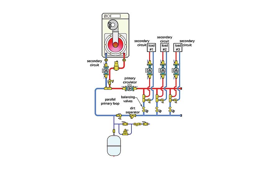
The system shown in Figure 4 on the previous page uses a parallel primary loop to connect the boiler with each load. A dedicated primary circulator is required to move flow through the primary loop whenever any load circuit is active.
Figure 5 on the previous page shows a system with a hydraulic separator that replaces the primary loop. This eliminates the need for a primary circulator. It also eliminates the need for dedicated air and dirt separators since these functions are handled by the internal coalescing media in the hydraulic separator.
Less transformers: Ever been in a mechanical room where there’s a half-dozen or more transformers mounted on 4-by-4 J-boxes and buzzing away 24/7? Figure 7 shows an example of such a situation. There’s a transformer located within each of those red clouds.

Put your hand on any active transformer and it feels warm. That’s because they’re sitting there converting electricity into heat through their primary windings regardless of whether there is an active load on their secondary winding. The installed cost of multiple transformers is certainly more than the transformers themselves. Each needs a J-box and associated wiring. Multiple transformers also set the stage for problems if connected in parallel without proper “phasing.”
Consider using a single larger transformer, such as one with a 100 VA rating, rather than several smaller transformers. Also strive for control arrangements that turn off transformers when the portion of the system they serve is not needed. Why let the transformer(s) in a cooling system operate during the heating season or vice versa? The electrical energy you save through reductions in control transformers is probably not going to be huge, but every bit helps.
Fewer fittings: Years ago I used to think of a box full of fittings and shutoff valves as incidental to the overall cost of a hydronic system. That’s definitely not the case today.
A 2014 estimating manual puts the installed cost of a 1-in. copper x male adapter fitting at $12.26. That adds almost $25 to the cost of installing a 1-in. valve you might have nonchalantly purchased with FPT connections (see Figure 8). My advice is to get away from installing threaded adapter fittings whenever possible.
You might also want to consider buying a quality tube bender and fabricating bends in tubing rather than installing elbows, as shown in Figure 9.
Less antifreeze: I have a saying about antifreeze — “The only good thing about antifreeze is it doesn’t freeze.” Glycol-based antifreeze decreases the heat capacity of the fluid relative to water. This requires increased flow rate for the same heat transfer. The higher viscosity of glycol-based antifreeze also adds significantly to head loss. At 120°, a 50% solution of propylene glycol increases head loss (at the same flow rate) by about 24%. When the flow rate is increased to compensate for reduced heat capacitance, the head loss goes up by 47%! That translates in more pumping power and higher operating cost.
As many of you have discovered, glycol-based antifreeze also has a propensity to weep through threaded fitting joints and create surface oxidation where water would either not leak or quickly evaporate without scaling. Last, but not least, filling a system with a 50% glycol solution can easily add a few hundred bucks to the installed cost.
So, where should antifreeze be used? Snow-melting systems and closed-loop solar collectors obviously need the protection it offers. In northern climates we also specify glycol in residential garage heating circuits and in homes that will be unoccupied for several consecutive winter days.
We used to specify antifreeze for floor heating systems in large slab-on-grade facilities such as highway garages. However, many of these buildings now have emergency generators that can keep running during a prolonged power outage. With constant circulation ”stirring” heat around in a large concrete slab, it could take several cold days before water in the slab circuits would be in danger of freezing, even if the heat source was not operating. Given these favorable odds we now avoid antifreeze in this type of facility.
Why less is more: It’s always a bit precarious to write about hardware being removed from systems. That hardware produces income for its manufacturer right down to the professional who installs it.
It’s nothing personal or vindictive that prompts me to discuss eliminating certain hardware. Instead, it’s to help ensure that average consumers can view hydronic heating as an affordable, efficient and understandable technology — something they want in their home or places of business.
That goal requires periodic “self-examination” of what we do as professionals and as an industry. We want to build market share not parts counts. Why build the space shuttle when our clients need a Piper Cub?
For Siegenthaler’s full article in pdf form, read here.
Looking for a reprint of this article?
From high-res PDFs to custom plaques, order your copy today!


")
