Myths and methods for protecting boilers against flue-gas condensation

Neptune was the god of freshwater and the sea in Roman religion. Speaking of myths, there are some when it comes to protecting boilers against flue-gas condensation.
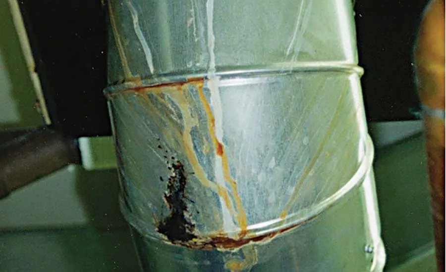
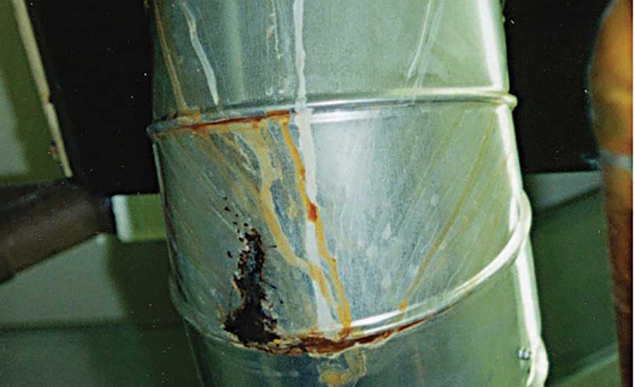
Figure 1 shows the results after only one year of operation. Photo credit: John Siegenthaler.
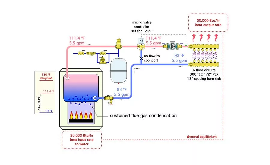
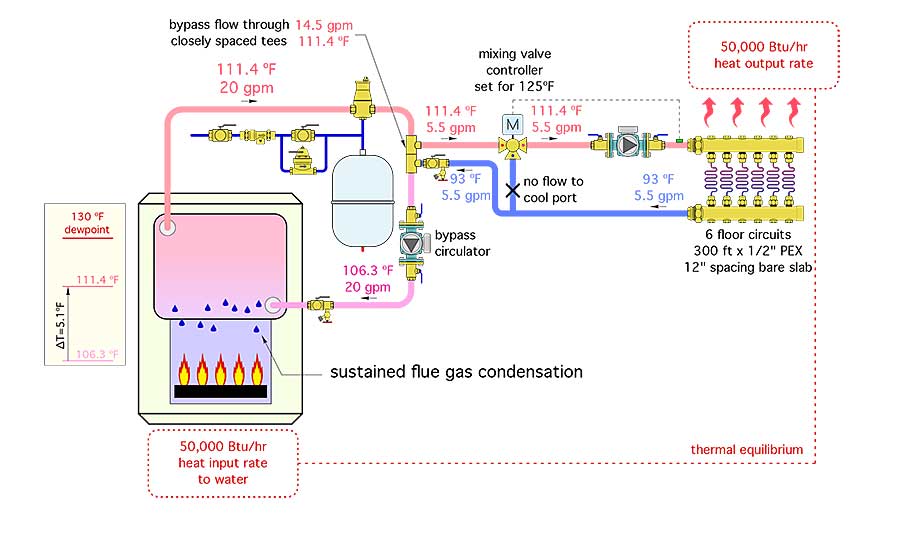
The system in Figure 2 does NOT measure boiler inlet temperature. Photo credit: John Siegenthaler.
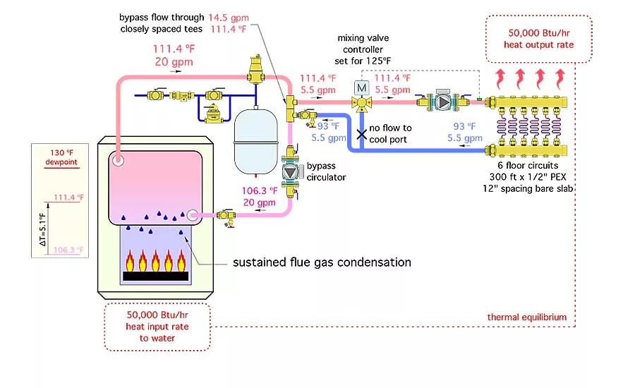
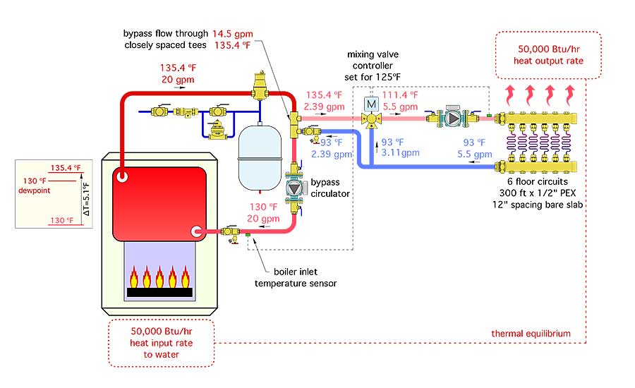
The system in Figure 3 adds a bypass circulator between the boiler and mixing valve. Photo credit: John Siegenthaler.
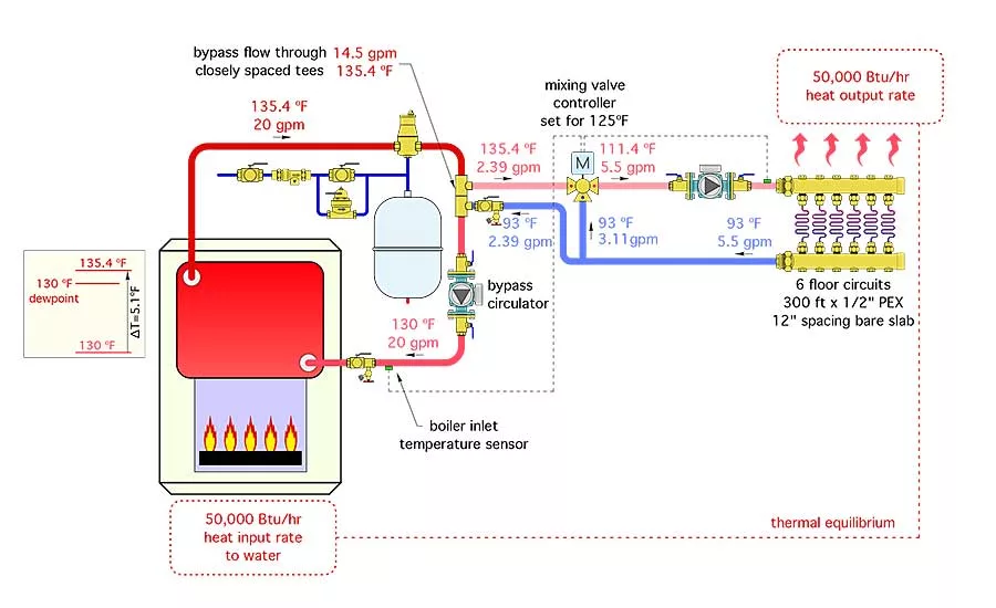
The system in Figure 4 uses a mixing valve controller that measures boiler inlet temperature. Photo credit: John Siegenthaler.
Here’s a statement anyone in the hydronics industry needs to remember:
All boilers that aren’t designed to operate with sustained flue-gas condensation should be protected against sustained flue-gas condensation.
The latter includes almost all cast-iron sectional boilers, steel boilers and copper-tube boilers. These boilers are not intended to operate with sustained flue-gas condensation. But, as a former colleague of mine once said: “Every boiler can be a condensing boiler.” After pausing to enjoy the confused looks from his audience, he went on to clarify his statement. “Given the right operating conditions, every boiler can be a condensing boiler.”
That statement is absolutely true. If the combustion-side surfaces of any boiler’s heat exchanger drop to or below the dew-point temperature of the exhaust gases, condensate will form in any boiler burning a hydrocarbon fuel such as natural gas, propane, fuel oil, firewood or pellets. This condensate is a mixture of water and several other chemicals that make every drop a nasty, hot acid with a pH in the range of 4.0. This condensate will aggressively attack ferrous metals as well as copper. It will chemically eat away at the boiler’s heat exchanger as well as the inside of the vent connector. Figure 1 shows the results after only one year of operation.
The presence or absence of sustained flue-gas condensation is determined by the temperature of the water entering the boiler and the air/fuel ratio at which combustion occurs. Of these, only the boiler inlet water temperature is easily controllable by how the boiler is applied.
Several decades ago, sustained flue-gas condensation was seldom a problem in hydronic systems. That’s because they were designed around heat emitters that forced the system to operate at relatively high water temperatures, typically in the range of 180° to 200° F.
During a “cold start” condition, a small amount of intermittent flue-gas condensation would form within the boiler. However, the operating conditions for these older, relatively high-temperature systems quickly increased the water temperature entering the boiler above the dew point and any initial condensate quickly evaporated. This situation occurs in every boiler during a cold start and generally is not a problem.
What has changed is the water temperature at which many modern hydronic systems operate. When radiant panel heating made its comeback in North America beginning in the 1980s, conventional boilers began to be paired with low-temperature distribution systems. This is where the ugly issue of sustained flue-gas condensation began appearing.
The North American hydronics industry struggled with this issue for several years. Various arrangements of circulators, valves and pipes were connected to boilers to try to prevent this condensation. Some worked and some didn’t. Hindsight shows only the methods that respected the first law of thermodynamics were successful. Try as you might, you will never get around this law.
Respecting the law
Fortunately, there are legitimate ways to avoid sustained flue-gas condensation when a conventional boiler is paired up with a low-temperature distribution system. Here is the bottom line:
The only way to avoid sustained flue-gas condensation is to monitor the boiler’s inlet water temperature and react to that temperature by limiting the rate at which heat moves from the boiler into the distribution system.
This requires the use of a mixing assembly between the boiler and distribution system.
The mixing assembly must determine if the distribution system is extracting heat faster than the heat source is generating heat. If heat dissipation exceeds heat production, thermodynamics demands the fluid temperature in the system will drop until the rate of heat extraction by the distribution system equals the rate of heat production by the boiler. If this requires the boiler to operate well below the dew point of its flue gases — so be it! Thermodynamics “doesn’t care” if the boiler is condensing; it only cares about balancing heat dissipation with heat production.
A properly installed and controlled mixing assembly protects the boiler by reducing the rate of heat flow from the boiler into the distribution system whenever the boiler temperature approaches or falls below a specified minimum operating temperature. This partially “unloads” the boiler from the distribution system, allowing its temperature to quickly rise above condensing conditions. This action “lifts” the combustion side of the boiler’s heat exchanger above the dew point of the exhaust gases.
Protects me or protects me not?
Figures 2, 3 and 4 illustrate situations in which a conventional boiler is and is not protected from flue-gas condensation. These systems all use a 3-way mixing valve to control the temperature of the water going to the distribution system. The manifold station in each system serves 6 floor-heating circuits, each being 300 ft. of 1/2-in. PEX tubing embedded at 12-in. spacing in a 4-in.-thick bare concrete slab. All these systems have a conventional boiler with a rated output of 50,000 Btu/h, and a boiler high-limit setting of 180°. In each case, the controller operating the mixing valve is set with the intention of maintaining a supply temperature of 125° to the manifold station.
The system in Figure 2 does NOT measure boiler inlet temperature. The water temperatures shown are those required based on a thermodynamic heat balance (e.g., where the rate of heat dissipation of the distribution system matches the rate of heat generation by the boiler with the boiler in continuous operation). In this case, the distribution system requires supply water at 111.4° to dissipate 50,000 Btu/h.

Because the mixing valve controller is trying to achieve a supply water temperature of 125° and only has water at 111.4° available from the boiler, the hot port of the mixing valve is fully open and the cool port completely shut. Hence, the mixing valve is simply “passing through” the entering water stream directly to the manifold station. No mixing occurs.
All water exiting the return manifold flows directly back to the boiler at 93°. This temperature is low enough to cause sustained flue-gas condensation within the boiler. This situation demonstrates that a mixing system that does not monitor and react to boiler inlet temperature cannot protect the boiler.
The system in Figure 3 adds a bypass circulator between the boiler and mixing valve. The 3-way mixing valve is correctly coupled to the boiler
bypass piping using a pair of closely spaced tees. These tees provide hydraulic separation between the bypass circulator and the distribution circulator. The intent of the bypass circulator is to mix higher-temperature water leaving the boiler into the cooler water flow returning from the distribution system and thus boost boiler inlet temperature.
The temperatures shown are again those mandated by a thermodynamic balance between heat dissipation by the distribution system and heat production by the boiler. Although the bypass circulator increases the flow rate through the boiler, it cannot adjust the rate of heat transfer to the
distribution system relative to the rate of heat production in the boiler. To dissipate the 50,000 Btu/h added to the water by the boiler, the manifold station still only requires 111.4° water at a 5.5-gpm flow rate and returns the same flow at 93°. The hot port of the mixing valve is again fully open and passing all entering hot water directly to the manifold station. No mixing occurs in the mixing valve.
The bypass circulator and boiler loop does create a second mixing point at the lower of the two closely-spaced tees. The mixing at this location slightly boosts boiler inlet temperature, but not high enough to prevent flue-gas condensation within the boiler. Installing a larger bypass circulator would increase the flow rate through the boiler and slightly boost the boiler inlet temperature. The temperature rise across the boiler would decrease in response to the higher flow rate. However, no matter how high the flow rate, the boiler’s inlet
temperature could never reach its outlet temperature. Sustained flue-gas condensation again will occur within the boiler.
This demonstrates the MYTH that a boiler bypass circulator, by itself, is insufficient to protect the boiler.
The missing element is a mixing system that senses and reacts to boiler inlet temperature.
The system in Figure 4 uses a mixing valve controller that measures boiler inlet temperature. The operating logic within this controller gives priority to maintaining the boiler inlet temperature above a user-selected minimum value, which in this example will be 130°.
Notice that the water temperature entering the boiler now is 130°. Given the same 20-gpm flow rate through the boiler, the temperature rise across the boiler will only be 5.1° and its outlet temperature will be 135.4°. This higher water temperature now enters the hot port of the mixing valve.
Don’t assume
Because hot water now is available to the mixing valve at 135.4°, one might assume the mixing valve controller would adjust the valve for a mixed supply temperature of 125° (e.g., the setting of the mixing valve’s controller). However, if the water temperature supplied to the floor circuits was to increase, so would heat output from the floor. Under such conditions, the floor circuits would release heat faster than the boiler can add heat to the water. The resulting thermodynamic imbalance would force the water temperature entering the boiler to drop. The boiler inlet temperature sensor immediately would detect this and the mixing controller would reduce the rate at which hot water enters the hot port of the mixing valve until the boiler inlet temperature increased back to 130°.
Thus, the system in Figure 4 stabilizes at the conditions shown where the floor circuits continue to be supplied with water at 111.4° and release heat at 50,000 Btu/h and the boiler inlet temperature remains at the mixing valve controller’s set minimum value of 130°. A thermodynamic balance between the boiler and distribution system is achieved and boiler inlet temperature is high enough to avoid flue-gas condensation.
The key to the successful strategy shown in Figure 4 is a mixing assembly that senses and reacts to boiler inlet temperature. This detail was lacking in the systems shown in Figures 2 and 3.
The systems shown in this article use a motorized 3-way valve as the main component of the mixing assembly. Alternatives to this mixing method include motorized 4-way mixing valves and injection mixing using a variable-speed pump or a motorized 2-way injection valve. When properly applied, these mixing assemblies also can protect a conventional boiler against flue-gas condensation.
Stick with the same principle of measuring boiler inlet temperature and reacting to it by not allowing the distribution system to extract heat from the water flowing through it faster than the rate at which the boiler produces heat.
Always provide protection
There still are many situations where conventional boilers will be used to supply low-temperature distribution systems. Always provide boiler protection by using hardware that measures the boiler inlet temperature and reacts to it, when necessary, to prevent sustained flue-gas condensation.
This article was originally titled “Unintended consequences” in the August 2017 print edition of Supply House Times.
Read here for Unintended consequences in pdf form.
Looking for a reprint of this article?
From high-res PDFs to custom plaques, order your copy today!


