There are differences between rules of thumb and precise calculations
It's not always 500

One of the most commonly used formulas in hydronic heating design:
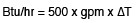
Representing this formula using symbols gives us the following:
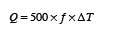
Formula 1
Where:
Q = Rate of heat transfer (Btu/h)
f = Flow rate (gallons per minute or gpm)
∆T = Temperature change (°F)
500 = fluid factor based on water as the system fluid
This formula can be used to determine the rate of heat transfer whenever the fluid flow rate and temperature change across a device such as a boiler, heat pump or heat emitter are known.
For example, assume that a flow meter indicates that water is passing through a boiler at 10.5 gpm. A thermometer on the inlet of the boiler reads 135° F, and another on the boiler outlet reads 154°. Formula 1 can be used to estimate the rate of heat transfer into the water:

This formula would give the same result if the boiler inlet temperature was 95°, and the outlet temperature was 114°. The ∆T of 114-95 is still 19°. In other words, it’s the change in temperature across the device, (rather than how “hot” the fluid is), in combination with flow rate, that determines the rate of heat transfer.
Another example would be reading the flow rate of a radiant floor tubing circuit at 1.1 gpm on a manifold flow meter, combined with a known supply. A temperature of 110 °, and a circuit return temperature of 93.5°. The rate of heat output of the circuit would be estimated as:
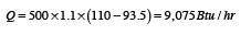
If you know both flow rate and ∆T, you can quickly estimate the rate of heat transfer to or from any device that’s part of a hydronic system.
Rule of thumb: Many of you know the rule of thumb that 1-gpm of water flow can carry 10,000 Btu/h along for the ride. This is based on Formula 1 when a temperature drop of 20° is assumed.
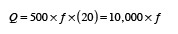
Formula 2
Where:
Q = Rate of heat transfer (Btu/h)
f = Flow rate of water (gpm)
Remember that Formula 2 only applies when a circuit operates with a 20° temperature drop. It also only applies when the heat transfer fluid is water. Beyond these constraints, the formula has even more assumptions built into it.
When it’s not 500: The number 500 in formulas 1 and 2 is based on the specific heat and density of the fluid being circulated, as well as some unit conversion factors. A more thermodynamically complete version of Formula 1 would look like this:
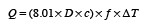
Formula 3
Where:
Q = Rate of heat transfer (Btu/h)
8.01 = Unit conversion factor
D = Density of fluid used (lb/ft3)
c = Specific heat of fluid used (Btu/lb/°F)
f = Flow rate of water (gpm)
∆T = Temperature change of fluid (°F)
Formula 4 shows the customary American units associated with the quantities in Formula 3. Notice that two conversion factors, shown in red, are needed to make the results come out with units of Btu/h. These two numbers, 60 divided by 7.49, are what result in the number 8.01in Formula 3.
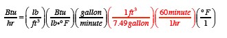
Formula 4
At some time back in math class, you learned that identical quantities that appear in both the top and bottom of fractions cancel each other out. If you do this with Formula 4, you end up with the same units (e.g., Btu/h) on both sides of the = sign. That’s absolutely necessary for the formula to be valid.
Formula 3 can be used with any fluid, provided the units are those stated, and that the density and specific heat of the fluid can be determined. Keep in mind that the density and specific heat of any fluid, change with the temperature of that fluid.
The density of water at 60° is 62.355 lb/ft3, and its specific heat at 60° is 0.99987 Btu/lb/°F. Putting these numbers into Formula 3 and simplifying yields:
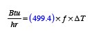
The value of 500 in Formula 1 comes from rounding off the 499.4. However, this value is based on the density and specific heat of water at 60°, which is quite low, relative to where most hydronic heating systems operate.
To better reflect the true heat transport properties of water and other fluids, the density and specific heat values used in Formula 3 should be based on the average temperature of the system fluid under design load conditions. For example, if the boiler supplies 140° water to a distribution system, and the return temperature is 120°, then the density and specific heat should be determined at the average water temperature of 130°.
To give you an idea of how things change, I’ve evaluated the product of (density x specific heat x 8.01), which I will call the “fluid factor” for water and some antifreeze solutions, and shown the results in Table 1 (rounded to the near whole number). For values at other temperatures, use the graph in Figure 1. In both cases, the units on the fluid factor are Btu/h/gpm/°F.
Table 1
You can see here that the changes in the fluid factor (density x specific heat x 8.01) are relatively small for a given fluid over the temperature range given. However, the fluid factor is noticeably different for different fluids. This is mainly due to the pronounced drop in specific heat of glycol solutions at higher concentrations.
Using the correct value of the fluid factor is especially important when designing glycol-based systems, such as used in snow-melting or solar-thermal systems.
Mental math: So does the number 500 still have a place in hydronic system design? Sure it does. When the system fluid is water, it’s a lot easier to make quick mental calculations using 500 instead of, say, 494. Estimating using the 500 factor certainly gets you in the ballpark. It’s also likely that other design or installation decisions could affect system performance more than using the non-temperature-adjusted value of the fluid factor for a given fluid type.
However, if you’re using a calculator, spreadsheet or other calculation tool, you should use the most accurate numbers possible. It’s just part of being a professional.
Looking for a reprint of this article?
From high-res PDFs to custom plaques, order your copy today!


