Understanding valve actuator selection
What facts do you need to make the right decision?
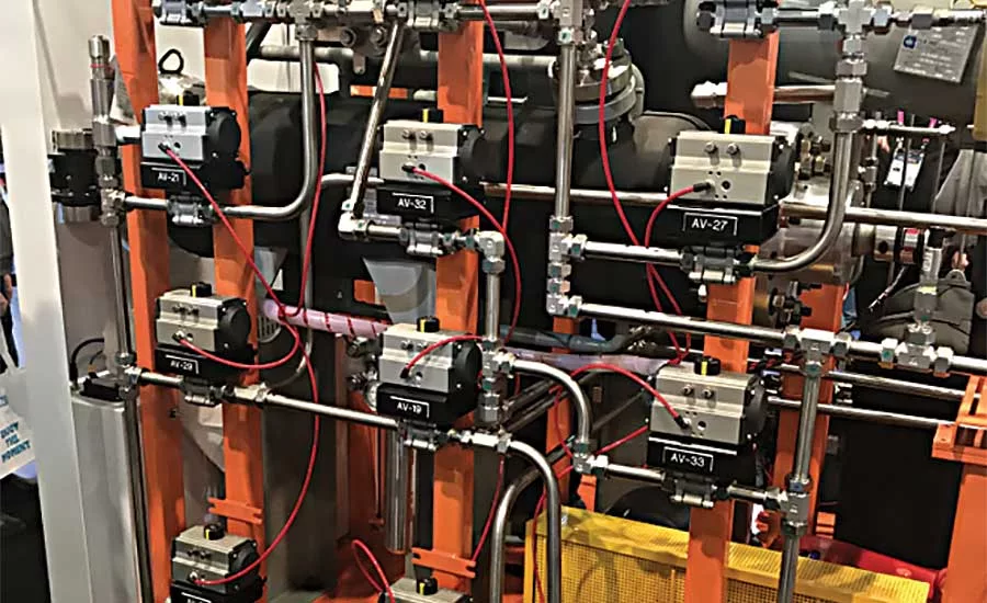
The decision to automate a valve is usually based on considerations such as safety, reliable operation and cost, among other factors. Photo courtesy of SVF Flow Controls.
The most Important step In developing a valve specification is to determine a sizing criterion.
The decision to automate a valve is usually based on one or all of the following considerations.
- Safety
- Reliable operation
- Control and process system performance
- Inaccessible or remote valve location
- Cost
- Excessive valve torque
- Emergency response and whether it is fail-safe
THE DISTINCT PURPOSE
All actuators have several distinct purposes that include:
Move the valve closure member (disc, ball or plug) to the desired position.
Hold the valve closure member in the desired position.
Seat the valve closure member with sufficient torque to provide the desired shutoff specification.
Provide a failure mode in the event of system failure. This may be fully opened, closed or as-is depending upon the application.
Provide the required rotational travel (90°, 180°, etc.). Valves requiring more than 90° of rotation include multi-ported valves.
Provide the required operating speed. All actuators may be regulated in cycle speed depending on the control circuit elements used.
PNEUMATIC AND ELECTRIC ACTUATORS COMPARED
At times, it is necessary for a process engineer to choose between a pneumatically or an electrically actuated valve for a process system. There are advantages to both styles, and it is valuable to have data available to make the best choice.
COMPATIBILITY (POWER SOURCE)
First and foremost in the selection of an actuator type (pneumatic or electric) is to determine the most effective power source for the actuator. Points to consider are:
- Power source availability
- Torque at the valve stem
- Failure mode
- Control accessories
- Speed of operation
- Frequency of operation
- Plant environment
- Size of valve
- System component costs
- System maintenance
The most practical pneumatic actuators utilize an air pressure supply of 40 to 120 psi (3 to 8 bar). Generally, they are sized for a supply pressure of 60 to 80 psi (4 to 6 bar).
Electric actuators often are used with a 110-VAC power supply, but are available with a wide variety of AC and DC motors in single-phase and three-phase.
HAZARDOUS AREAS
It is sometimes difficult to justify the use of electric actuators in a hazardous environment, but if compressed air is not available, or if a pneumatic actuator will not provide the operating characteristics required, then an electric actuator with a properly classified enclosure may be used.
Almost all electric actuator manufacturers have an option for a version of their standard product line that conforms with NEMA VII. Another source for hazardous area guidance is available from ATEX.
On the other hand, pneumatic actuators are inherently “explosion-proof.” When electric controls are used with pneumatic actuators in hazardous areas, they are generally more cost effective than electric actuators. Solenoid-operated pilot valves (which are electrical devices) may be mounted and powered in a nonhazardous area and piped to the actuator. Limit switches — for position indication — may be housed in a NEMA VII enclosure. The inherent safety of pneumatic actuators in hazardous areas makes them a practical choice in these applications.
SPRING RETURN
Another safety accessory widely specified in the process industries on valve actuators is the spring-return (fail-safe) option. Upon power or signal failure, a spring-return actuator drives the valve to a predetermined safe position. This is a practical and inexpensive option with pneumatic actuators and is an important reason for the wide use of pneumatic actuators throughout the industry.
Electric actuators are available with a spring return option or a battery backup system to provide predictable “failure” positioning.
PERFORMANCE CHARACTERISTICS
Before specifying a pneumatic or electric actuator for valve automation, it is important to consider a few of the key performance characteristics of each.
Duty cycle: Pneumatic actuators have a 100% duty cycle. In fact, the harder they work, the better they work. Electric actuators are most commonly available with 25% duty cycle motors. This means that to prevent overheating in high-cycle applications, the motor must rest frequently. Because most on-off automated valves remain idle 95% of the time, duty cycle is not usually an issue. With optional motors and/or capacitors, an electric actuator may be upgraded to 100% duty cycle.
Stalling: Pneumatic actuators may be stalled indefinitely without overheating. Electric actuators should not be stalled. Stalling an electric actuator draws excessive current, which generates heat in the motor and can cause damage. Torque switches or heat and current sensors often are installed in electric actuators to protect the motor.
Speed control: The ability to control the speed of a pneumatic actuator is an important advantage of the design. The simplest way to control the speed is to fit the actuator with a variable orifice (needle valve) at the exhaust port of the air pilot. Since electric actuators are geared motors, it is impossible to make them cycle faster unless a gearing change is made. For slower operation, a pulsing circuit may be added as an option.
Modulating control: In modulating service, an electric actuator interfaces well with existing electronic control systems and eliminates the need for electro-pneumatic controls. A pneumatic or electro-pneumatic positioner is used with pneumatic actuators to provide a means of controlling the valve position.
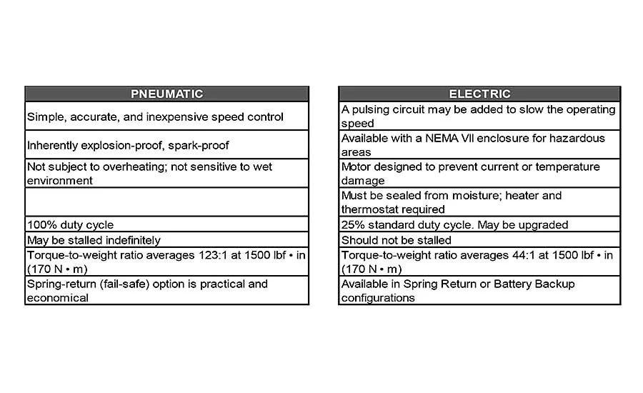
SUMMARY OF PNEUMATIC AND ELECTRIC ACTUATORS
This table of characteristics (Chart 1, to the left) summarizes the comparison of pneumatic and electric actuators.
ACTUATOR SIZING
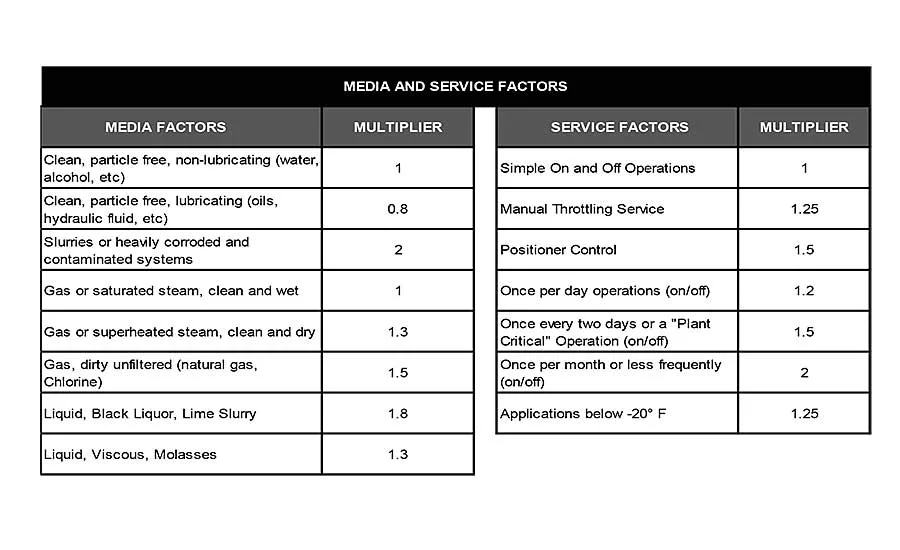
The most important step in developing an automated valve specification is to determine a sizing criterion. If a valve is to operate in a process handling clean liquids at moderate pressures and temperatures, the manufacturer’s published operating torque is usually adequate for actuator sizing. Under certain conditions, however, the torque required to operate a valve may increase. In this case, a sizing safety factor may need to be applied based on the following guidelines in Chart 2 to the left.
NOTE: Consult the valve manufacturer for specific Safety Factor recommendations.
Looking for a reprint of this article?
From high-res PDFs to custom plaques, order your copy today!


