Avoid lightweight concrete for heated slabs
There are many ways to create radiant floor-heating panels.

During discussions of radiant-floor heating I occasionally hear someone mention the idea of using lightweight concrete to form a thin-slab radiant-floor panel.
There are many ways to create radiant floor-heating panels: Slab-on-grade, thin-slab, above-floor tube & plate, below-floor tube & plate and several “dry” panel underlayment systems. In this column we’ll focus our attention on thin-slab systems.
Figure 1 shows the cross section of a typical thin-slab radiant-floor panel.
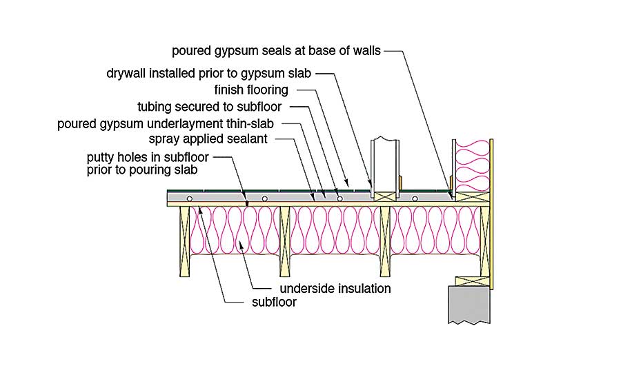
The concept is relatively simple: Secure the PEX tubing to the wooden subfloor using a “depth-controlled” pneumatic stapler. Pressure-test all the completed circuits to ensure no leaks. Then cover the tubing with a nominal 1.5 inches of poured cementitious material. The latter includes both poured gypsum underlayment and portland cement-based concrete. A finish floor such as ceramic tile can then be placed over the cured thin-slab.
Not on the list: During discussions of radiant-floor heating I occasionally hear someone mention the idea of using lightweight concrete to form a thin-slab radiant-floor panel. The term lightweight concrete tends to be used loosely within the context of radiant-floor heating. To many building professionals it describes almost any poured material that’s lighter than standard structural concrete.
However, there’s a big difference in the thermal properties of lightweight concrete compared to proven thin-slab materials such as poured gypsum underlayment. Lightweight concrete uses lighter aggregate in place of the crushed stone commonly used in structural concrete. Some mixes of lightweight concretes use expanded shale or vermiculites as their aggregate. Some mixes even use polystyrene beads as the aggregate.
Lightweight concrete is commonly used to increase the fire-resistance rating of wooden floors or decreasing sound transmission through floors. It also can be used to create lightweight masonry blocks that can be cut with a handsaw.
Depending on the mix design, the dry density of some lightweight concretes can be as low as 25 pounds per cubic foot. That’s about 1/6 the density of standard structural concrete. If you’re an architect or structural engineer designing columns and girders for multistory buildings, that weight reduction is a substantial benefit.
Many suppliers of lightweight concrete also promote their products’ ability to reduce heat flow through exposed building surfaces due to its high R-value. The millions of air cells in the lightweight aggregate are what make this possible. Unfortunately, higher R-value is precisely what you don’t want when selecting a slab material for a heated floor slab.
An internet search of lightweight concrete provides technical data for the density and thermal properties of several lightweight concrete products. Figure 2 is a plot of the R-value per inch of thickness for one manufacturer’s offerings, which range in density from 106 PCF to as low as 25 PCF. For comparison, the R-value of 1 inch of standard structural concrete (150 PCF) is about 0.1 ºF•hr•ft2/Btu.
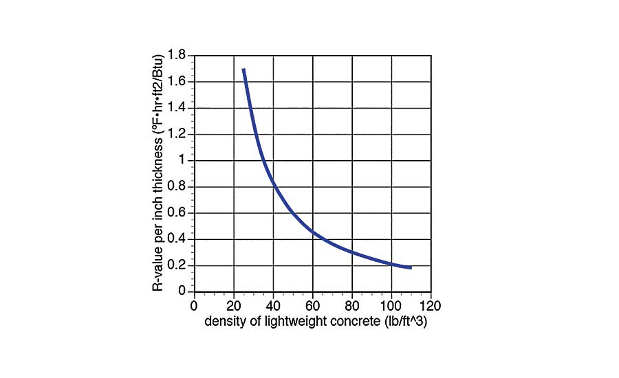
Notice the large increase in R-value as the density of the products decreases, especially for ultra-light mixes that use polystyrene beads for their aggregate.
What would happen if lightweight concrete is used as the slab material in a thin-slab floor-heating system? I’m sure most of you suspect that heat transfer would go down as the R-value of the slab material goes up. You’re right! The tougher question is how much of a decrease in performance would occur and if it’s anything to be concerned about?
To answer this I used special software to perform “finite element analysis” (FEA) of a thin-slab system where the only variable was the R-value and density of the slab material. FEA looks at the details of conduction and convection heat transfer in situations where several materials are put together. It’s about the only practical way to get a handle on the complex thermal interactions that occur in such situations.
The thin-slab system I modeled assumed 1/2-inch PEX tubing placed at 12-inch spacing over a 3/4-inch-thick plywood subfloor with a 1.5-inch-thick slab on top. The top of this slab was covered with ceramic tile fully bonded to the slab. The underside of the plywood was insulated with R-11 fiberglass batt insulation. The air temperature above and below this assembly was assumed to be 70° F. The water in the tubing was assumed to be at 100°.
I ran the analysis of this assembly assuming slab densities of 150, 106, 75 and 25 PCF, along with the associated thermal conductivity data listed by the lightweight concrete supplier. The results of these simulations are shown in Figure 3.
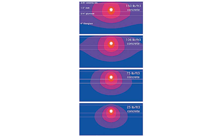
The colored areas in Figure 3 represent ranges of temperature. The higher temperatures are shown in red, the cooler temperatures in dark blue. Notice how the colored regions get closer together as the R-value of the slab material increases. This means heat is not spreading out as well across the floor. The closer the colored regions are to each other, the steeper the drop in floor-surface temperature when moving away from the tubing. To see this, look at Figure 4, which plots the predicted floor-surface temperature for the various slabs, from 150 PCF (standard structural concrete) down to 25 PCF (very low-density lightweight concrete).
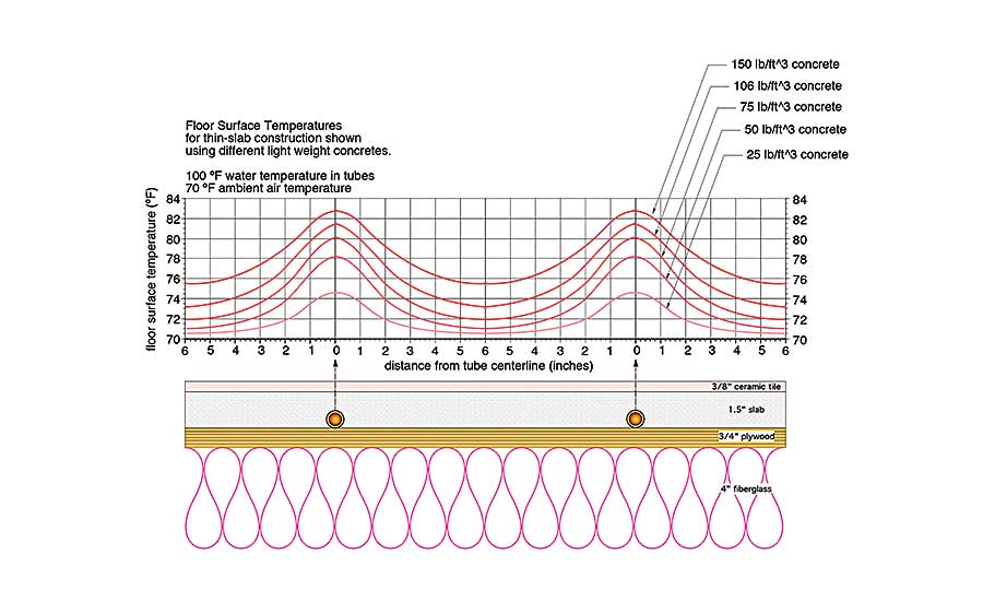
The area under these floor-surface temperature curves is proportional to the heat output from the floor. The lower the curve is on the graph, the lower the heat output from the floor. To put it into perspective, the FEA simulations predict the output of the slab using 75 PCF lightweight concrete is about 58% of what the output would be if the slab were standard structural concrete. The output of the slab using 25 PCF lightweight concrete is only about 22% of the slab using standard concrete. The lesson here: The lighter the slab the “lighter” its heat output.
Just ‘smoke’ that floor: About now some of you probably are thinking you could “overpower” the poor thermal performance of the lightweight concrete by increasing the water temperature in the embedded tubing. You’re right again! But remember that old saying: “It’s not nice to fool mother nature?” It turns out she has a surprise in store for those who use their water- temperature controls to compensate for a poorly conducting slab. Figure 5 shows the surface- temperature profiles that result from upping the water temperature in a thin-slab made of 75 PCF lightweight concrete.
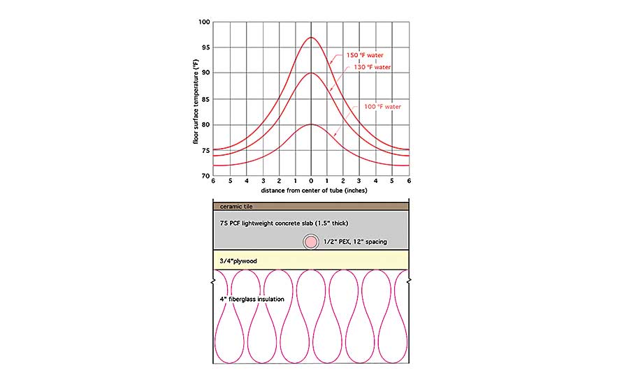
The higher the water temperature the greater the heat output and the greater the temperature difference between the peak and the valley of the curves. With 150° water in the tubing the floor surface temperature drops 22°, (from 97 to 75°) over just 6 inches of horizontal distance. That wide change in temperature is called “striping.” It’s undesirable from a comfort standpoint, as well as from the standpoint of increasing stresses within the flooring materials. The striping would be even worse for slabs using lower-density lightweight concrete.
The homeowner would have no problem locating the tubing in the floor. After some time, materials such as vinyl flooring or carpet might even permanently change color directly above the tubing. Wouldn’t that make a nice “distressed motif” to discuss during dinner parties?
See the light: For those who think stripes look better on tigers than on our clients’ floors, the message is simple: Don’t use slab materials with R-values significantly higher than proven mixes such as structural concrete or poured gypsum underlayment.
If you happen to hear the term “lightweight concrete” come up in a discussion on floor heating, make sure the person proposing its use knows what’s likely to happen. Before committing to anything other than structural concrete or poured gypsum underlayment, get the R-value data from the manufacturer and compare it to proven products.
Otherwise that new lightweight slab may set you up for some heavy callbacks.
To read Siegenthaler’s article “Hydronics: Don't take it lightly” in pdf form, please see here.
Looking for a reprint of this article?
From high-res PDFs to custom plaques, order your copy today!


