10 Melting Matters
These important details help melt snow rather than your technical support line.

Most suppliers who’ve worked within the hydronic radiant heating market have no doubt been asked for assistance with snowmelting applications. The hardware used for snowmelting overlaps in part with that used for hydronic radiant heating systems.
However, the differences between hydronic radiant floor heating and snowmelting go far beyond whether the tubing is installed inside or outside a building. Failure to recognize and address key design issues with snowmelting can lead to very disappointing results and costly corrections. To help avoid these pitfalls I’ve assembled a list of 10 essential details for successful snowmelting applications.
The idea is to MELT the snow and ice and then allow most of the melt water to drain away rather than evaporate or refreeze. Changing snow (ice crystals) into water requires about 144 Btu/pound. To melt 1-inch of typical density (about 6 lb/ft3) snow per hour requires a heat input of about 75 Btu per square foot of pavement. That in itself is about three times the typical rate of heat delivery to a residential radiant floor at design load conditions. Evaporating the melt water requires an additional 970 Btu/pound - almost seven times more energy than needed to change the snow to water. Some of this evaporation energy comes from the atmosphere depending on relative humidity and air temperature. Still, having to operate the snowmelting system for a prolonged “post-melt” period just to evaporate water that hasn’t drained from the pavement surface is very energy intensive and thus very expensive. The alternative of turning the system off before the pavement is dry is even worse. Doing so can turn a wet surface into glare ice.
Always slope pavement surfaces toward drains, and be sure those drains lead the melt water to where it will not freeze. In locations without storm sewers this may require drywell(s). Be sure you assess the drainage requirements when discussing snowmelting with clients. Also keep in mind that the same drainage system will have to handle heavy rainfall events during warmer weather.
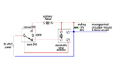
It’s relatively easy to enable the snowmelting system to operate when it’s not snowing. I prefer using a simple selector switch for each snowmelting zone. The “off” setting disables snowmelting. The “manual” setting turns it on and leaves it on. The “auto” setting puts melting under the control of the snow/ice detector system. Figure 1 shows an electrical schematic for this control configuration.
The “manual” mode usually requires the owner to remember to turn the system off. Forgetting to do so could obviously lead to some high fuel bills. To prevent this I suggest installing a timer circuit that disables melting in the manual mode after a period of say 12 hours. If there’s still snow to be melted the owner can dial in additional operating time as necessary. I also recommend installing a prominently located indicator light that remains on when the system is in melting mode. This should prompt someone who’s set the system in manual melt mode to reset the selector switch before leaving the building for several days.
The following tube spacings are suggested depending on the class of the snowmelting application:

Here’s an example. A 220-foot-long snowmelting circuit with tubing spaced 12 inches apart must deliver 200 Btu/hr/ft2 at design load. The circuit operates with a 50% solution of propylene glycol and has a design temperature drop of 20°F. The required flow rate is:
Don’t even think about trying to shove this flow through 1/2-inch or 5/8-inch tubing. You’ll need at least 3/4-inch tubing to handle this flow rate at a reasonable head loss.
The head loss of a 220-foot-long circuit of 3/4-inch PEX carrying 50% propylene glycol at 4.89 gpm is 34.5 feet. That’s just about out of the range of small wet rotor circulators. Changing the circuit to 1-inch PEX at the same flow rate drops the head loss to 10.5 feet. In this case, using the 1-inch tube will cut the electrical operating cost of the system to about 1/3 that of using 3/4-inch tube. Granted, some well-heeled clients who install snowmelting may not care about the operating cost of the circulator, but the professional who designs the system should. Why not make a choice that ultimately will pay for itself several times over during the life of the system?
However, when the fluid the system is handling is literally “ice cold” at start-up you also need to protect against condensation and frost in other parts of the system. Here’s what to keep an eye on:
Heat exchangers cost enough without having to replace them as the result of a preventable freeze. My suggestion is to include a temperature setpoint controller on the leaving water side of the heat exchanger. The electrical contacts of this controller would only allow the antifreeze side circulator to operate once the water leaving the heat exchanger has reached a reasonable temperature of say 100° F. They would also open if the water side temperature dropped to say 50°F.
You only get one opportunity to do it right. Use a proven product like 25 psi or higher compressive strength extruded polystyrene, and always install it on properly tamped subgrade. If the pavement could have heavy commercial vehicles on it, I suggest a minimum of 60 psi rated extruded polystyrene.
Leave some small gaps between adjacent sheets of insulation so the water that inevitably percolates down through cracks in the pavement surface will not be trapped above the insulation where it could refreeze and heave the pavement. Be sure there is high percolation soil or a bed of gravel under the insulation to allow this water to dissipate rather than pond under the insulation.
Zoned snowmelting systems are best controlled with in-slab snow detectors rather than above-pavement snow-switches. It’s important that any automatic snow detectors be placed to respond to likely drifting patterns. Think about prevailing winds and vertical surfaces such as retainer walls or shrubs that rise above the upwind side of the paved areas. Drifts can also form at the downwind corners of buildings located adjacent to pavements. Snow can also pile up just outside the overhang line of roofs located upwind from the pavement. Plan your zones accordingly.

The schematic in Figure 3 shows the concept of a multiple mod/con boiler system supplying snowmelting, high capacity domestic water heating, and zoned space heating. The hydraulic separator keeps the peace between all the circulators and provides air and dirt separation. The space heating subsystem uses a variable-speed pressure-regulated circulator in combination with zone valves to minimize pump power. The snowmelting subsystem protects the heat exchanger against freezing as described earlier. Because mod/con boilers are used, no mixing device is required in the snowmelting subsystem. The cooler they operate, the more efficient they are.
There you have it - 10 details to help ensure your future snowmelting systems keep the snow shovels, blowers and plows at rest and provide years of efficient service.
Most suppliers who’ve worked within the hydronic radiant heating market have no doubt been asked for assistance with snowmelting applications. The hardware used for snowmelting overlaps in part with that used for hydronic radiant heating systems.
However, the differences between hydronic radiant floor heating and snowmelting go far beyond whether the tubing is installed inside or outside a building. Failure to recognize and address key design issues with snowmelting can lead to very disappointing results and costly corrections. To help avoid these pitfalls I’ve assembled a list of 10 essential details for successful snowmelting applications.
1. Always plan for drainage.
Installing snowmelting without proper drainage is like doing an indoor pool without a dehumidifier - both reduce cost and both will quickly get you in big trouble.The idea is to MELT the snow and ice and then allow most of the melt water to drain away rather than evaporate or refreeze. Changing snow (ice crystals) into water requires about 144 Btu/pound. To melt 1-inch of typical density (about 6 lb/ft3) snow per hour requires a heat input of about 75 Btu per square foot of pavement. That in itself is about three times the typical rate of heat delivery to a residential radiant floor at design load conditions. Evaporating the melt water requires an additional 970 Btu/pound - almost seven times more energy than needed to change the snow to water. Some of this evaporation energy comes from the atmosphere depending on relative humidity and air temperature. Still, having to operate the snowmelting system for a prolonged “post-melt” period just to evaporate water that hasn’t drained from the pavement surface is very energy intensive and thus very expensive. The alternative of turning the system off before the pavement is dry is even worse. Doing so can turn a wet surface into glare ice.
Always slope pavement surfaces toward drains, and be sure those drains lead the melt water to where it will not freeze. In locations without storm sewers this may require drywell(s). Be sure you assess the drainage requirements when discussing snowmelting with clients. Also keep in mind that the same drainage system will have to handle heavy rainfall events during warmer weather.
Figure 1.
2. Consider off/manual/auto selector switches as part of the snowmelt control system.
Although it seems contradictory, there are times when snow needs to be melted and it’s not snowing outside. A patio or walkway at a weekend house is a good example. Perhaps it snowed when nobody was home, the snowmelting system was turned off to save fuel, and upon arrival there’s a foot of snow on the walkway that needs melting. Drifting snow can also create a need for snow melting when it may not be snowing.It’s relatively easy to enable the snowmelting system to operate when it’s not snowing. I prefer using a simple selector switch for each snowmelting zone. The “off” setting disables snowmelting. The “manual” setting turns it on and leaves it on. The “auto” setting puts melting under the control of the snow/ice detector system. Figure 1 shows an electrical schematic for this control configuration.
The “manual” mode usually requires the owner to remember to turn the system off. Forgetting to do so could obviously lead to some high fuel bills. To prevent this I suggest installing a timer circuit that disables melting in the manual mode after a period of say 12 hours. If there’s still snow to be melted the owner can dial in additional operating time as necessary. I also recommend installing a prominently located indicator light that remains on when the system is in melting mode. This should prompt someone who’s set the system in manual melt mode to reset the selector switch before leaving the building for several days.
Figure 2.
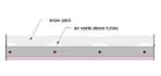
3. Never exceed 12-inch tube spacing.
Although it’s possible to get acceptable performance in certain floor heating applications using 18-inch tube spacing this is never the case with snowmelting. Tubing spaced wider than 12 inches will cause “tenting” as the snow melts. The warmer pavement surface directly above the tubing creates small elongated igloos in the snow as shown in Figure 2. The stationary air trapped between the snow surface and pavement acts like insulation, and slows the rate of further melting.The following tube spacings are suggested depending on the class of the snowmelting application:
- Class 1 systems: (residential applications) 9 to 12
inches
- Class 2 systems: (high melt rate residential / commercial) 6 to 9
inches
- Class 3 systems: (critical applications where pavement must remain snow-free at all times) 4 to 6 inches
4. Remember that flow is critical.
A radiant floor operating at design load conditions may deliver around 35 Btu/hr/ft2. A class 2 snowmelting system in a location like Buffalo, NY, must deliver about 200 Btu/hr/ft2. That’s almost six times more heat delivery per square foot than the floor heating system. Assuming the same temperature drop across the circuits in both cases, the higher rate of heat delivery must be handled by increased flow rate, and this usually requires larger tubing.Here’s an example. A 220-foot-long snowmelting circuit with tubing spaced 12 inches apart must deliver 200 Btu/hr/ft2 at design load. The circuit operates with a 50% solution of propylene glycol and has a design temperature drop of 20°F. The required flow rate is:
Don’t even think about trying to shove this flow through 1/2-inch or 5/8-inch tubing. You’ll need at least 3/4-inch tubing to handle this flow rate at a reasonable head loss.
The head loss of a 220-foot-long circuit of 3/4-inch PEX carrying 50% propylene glycol at 4.89 gpm is 34.5 feet. That’s just about out of the range of small wet rotor circulators. Changing the circuit to 1-inch PEX at the same flow rate drops the head loss to 10.5 feet. In this case, using the 1-inch tube will cut the electrical operating cost of the system to about 1/3 that of using 3/4-inch tube. Granted, some well-heeled clients who install snowmelting may not care about the operating cost of the circulator, but the professional who designs the system should. Why not make a choice that ultimately will pay for itself several times over during the life of the system?
5. Protect conventional boilers against condensation.
If a conventional boiler (e.g., one with a cast-iron, steel, or copper tube heat exchanger) is used as the heat source for a snowmelting system, it must be protected against sustained flue gas condensation. This is easily handled by a modern mixing system with boiler inlet temperature sensor.However, when the fluid the system is handling is literally “ice cold” at start-up you also need to protect against condensation and frost in other parts of the system. Here’s what to keep an eye on:
- All interior piping serving snowmelt manifold stations
should be fully insulated and vapor sealed to prevent surface condensation.
Don’t get sloppy at pipe supports and valves. Be sure the insulation runs
through the pipe supports with the necessary support sleeves, and that it also
surrounds valve bodies. If not, you’ll surely see dripping and rusting hardware
in short order. Also, be sure the butt ends of the insulation are bonded
together.
- Insulate the circulator volute, or locate it where condensation dripping from it will not be a problem. Also position the junction box on a wet-rotor circulator carrying cold glycol at the top of the motor to keep it as warm (and condensation-free) as possible. Another option is to use a non-wet-rotor circulator with a coupling assembly to keep the motor warm enough to prevent condensation.
6. Protect heat exchangers against freezing.
Consider what could happen when antifreeze at sub-freezing temperatures starts flowing through a typical flat plate heat exchanger, several minutes before warm water makes it through the other side of that heat exchanger. Such heat exchangers have very little thermal mass in comparison to their internal surface area. It’s very possible the water side of the heat exchanger could clog with ice crystals before heated water arrives. A hard freeze could also occur if the water side circulation stopped due to a circulator failure or boiler lockout.Heat exchangers cost enough without having to replace them as the result of a preventable freeze. My suggestion is to include a temperature setpoint controller on the leaving water side of the heat exchanger. The electrical contacts of this controller would only allow the antifreeze side circulator to operate once the water leaving the heat exchanger has reached a reasonable temperature of say 100° F. They would also open if the water side temperature dropped to say 50°F.
7. Always insulate under heated pavements.
It’s the same reasoning as a heated floor slab. The idea is to direct the heat where you want it (e.g., the top of the pavement) rather than into an almost infinite heat sink (the earth).You only get one opportunity to do it right. Use a proven product like 25 psi or higher compressive strength extruded polystyrene, and always install it on properly tamped subgrade. If the pavement could have heavy commercial vehicles on it, I suggest a minimum of 60 psi rated extruded polystyrene.
Leave some small gaps between adjacent sheets of insulation so the water that inevitably percolates down through cracks in the pavement surface will not be trapped above the insulation where it could refreeze and heave the pavement. Be sure there is high percolation soil or a bed of gravel under the insulation to allow this water to dissipate rather than pond under the insulation.
8. Lift the tubing to mid-slab height during pour.
The transient response of an ice-cold concrete slab is slow enough without extra inches of concrete between the tubing and top of slab. Be sure to communicate how important this is to those responsible for placing the concrete. Make sure it’s clearly described and drawn in your documentation. Provide a detail for control joints that keeps the tubing down under the saw cuts.9. Identify possible drifting locations.
If the pavement being melted includes areas where snow drifting is likely, consider zoning the system. Drifted areas often require longer melting times relative to sheltered areas. Why run the entire snowmelt system if only certain portions of the pavement need this longer melting time?Zoned snowmelting systems are best controlled with in-slab snow detectors rather than above-pavement snow-switches. It’s important that any automatic snow detectors be placed to respond to likely drifting patterns. Think about prevailing winds and vertical surfaces such as retainer walls or shrubs that rise above the upwind side of the paved areas. Drifts can also form at the downwind corners of buildings located adjacent to pavements. Snow can also pile up just outside the overhang line of roofs located upwind from the pavement. Plan your zones accordingly.
Figure 3.
10. Consider a staged multiple boiler system.
One characteristic of snowmelting is that the loads are intense but relatively infrequent - at least in comparison to space-heating loads. Although one could supply a snowmelting system through a dedicated boiler, it often makes sense to use the same boiler system that heats the house and provides domestic water heating. The system can be configured with a stepped priority type control (e.g., domestic water heating is first priority, space heating is second priority, and snowmelting is third priority). This prevents the need to size the boiler system to simultaneously supply all loads at design values - which is very improbable. A staged boiler system can also provide the output to keep up with high domestic water heating demands.The schematic in Figure 3 shows the concept of a multiple mod/con boiler system supplying snowmelting, high capacity domestic water heating, and zoned space heating. The hydraulic separator keeps the peace between all the circulators and provides air and dirt separation. The space heating subsystem uses a variable-speed pressure-regulated circulator in combination with zone valves to minimize pump power. The snowmelting subsystem protects the heat exchanger against freezing as described earlier. Because mod/con boilers are used, no mixing device is required in the snowmelting subsystem. The cooler they operate, the more efficient they are.
There you have it - 10 details to help ensure your future snowmelting systems keep the snow shovels, blowers and plows at rest and provide years of efficient service.
Links
Looking for a reprint of this article?
From high-res PDFs to custom plaques, order your copy today!


