
During my three decades in the hydronics industry, I’ve heard terms that upon close scrutiny don’t accurately represent a concept or device. I even admit to using some of these terms myself, usually before I understood exactly what they meant, or considered what they might imply.
I’m sure most of you hear some of the terms we’re about to discuss on a daily basis. Many of you could even hold a reasonably clear peer-to-peer conversation using these terms because they’ve been around the industry for decades.
Still, it’s important to think how some of the terms we’re about to discuss could be misinterpreted by those new to hydronics, or by potential clients listening to a description of a hydronic system. In my opinion, some of them can foster misunderstandings about how the system operates or what it’s capable of doing. This can lead to unmet expectations, or even to systems that are doomed from Day One.
Here then is a list of expressions that I would like to stamp out in favor of more accurate verbiage.
Radiant tubing:This expression gets plenty of use in our industry. I’m sure I’ve used the word “radiant” to describe PEX or PEX-AL-PEX, or other tubing that happens to be part of a radiant panel construction. However, I have since concluded that this is not a wise pairing of words. Here’s why.
“Radiant tubing” suggests that the tubing we install in floors, walls and ceilings transfers heat to surrounding materials primarily by thermal radiation. For most installations, this is simply not true. Heat moves from the tubing to surrounding solid materials by conduction. Radiant heat transfer occurs only when the tubing is partially or totally surrounded by cooler surfaces with air gaps or a vacuum in between. In most radiant panels, radiant heat transfer plays a very minor role in getting heat from the water in the tubing to the surface of the panel.
I’m now convinced that this term has built a false confidence among some installers, who simply string “radiant tubing” through floor framing convinced it will miraculously beam out ample heat to produce toasty floors above.
Many have learned the hard way that this isn’t true. There’s nothing magical about any tubing that makes it glow in the dark, exude copious quantities of photons, or otherwise put forth large amounts of radiant energy to surrounding materials. So why don’t we just call it what it is: PEX, PEX-AL-PEX, PERT or composite rubber tubing?
Head pressure
There really is no such thing as “head pressure.” Certainly there is “head” and there is “pressure,” but they are two different (albeit related) concepts. Let’s get specific.Head is the totalmechanical energycontained by the fluid at a point in the system. In North America, that energy is expressed in feet. This unit comes from mathematically simplifying the number of ft•lbs (pronounced foot pounds) of mechanical energy each pound of fluid contains. Here’s how the units work out.
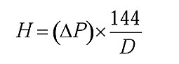
Formula 1.
We use circulators to convert electrical energy into head energy. Because they’re not 100% efficient, they convert some of the electrical energy supplied to them into head, and the remainder into heat. A typical wet-rotor zone circulator that’s well-matched to its circuit converts about 20% to 25% of the electrical input energy to head. Modern ECM-based circulators running at full speed, and well-matched to their circuit can almost double this wire-to-water efficiency.
So where does pressure come into this discussion? Here’s the way I like to explain it. Theevidencethat head energy has been added to a fluid as it passes through a circulator is an increase in pressure between the circulator’s inlet and outlet port. Theevidencethat head energy has been removed from a fluid as it flows through a device is a decrease in fluid pressure.
The increase or decrease in pressure associated with adding or removing head energy from a fluid can be calculated usingFormula 1.
where:
H = head added or removed (feet of head);
∆P = differential pressure (psi);
144 = a constant needed based on the units used; and
D = density of fluid (lb/ft3).

Figure 1
Lightweight concrete
On several occasions I’ve heard individuals say they plan to cover tubing stapled to a subfloor with lightweight concrete. In most cases, what they meant waspoured gypsum underlayment.Although there is such a thing as lightweight concrete, it’s definitely not the same as poured gypsum underlayment. The latter has been successfully used for years in many floor heating systems. The former is something that shouldneverbe used for such applications due to its low thermal conductivity.
Figure 1shows how the surface temperature of a heated “thin slab” varies based on the density of the concrete forming the slab. Notice how the floor surface temperature curves shift downward (indicating reduced heat output) as the density of the concrete used for the slab decreases. The lighter the concrete, the lower its thermal conductivity and the poorer the slab performs.
All other conditions being equal, the heat output of thin slab constructed with lightweight concrete having a density of 25 lb./ft3 is only about 22% of a slab constructed with 150 lb./ft3 density concrete.
Use of lightweight concrete for a heated floor slab can be a thermal disaster. If you hear someone suggesting such use, be sure to tell them the resulting system will be light in weight, andvery lightin performance.
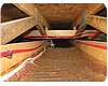
Figure 2
Joist heating
Is it floor joists we’re trying to warm or the floor above? Although I’m sure most of you know the answer,Figure 2on the previous page demonstrates that not everyone does.It’s hard to imagine a less effective way of installing tubing when the intent is to warm the upper surface of the floor. The thermal resistance between the water in tube to the top surface of the floor in Figure 2 is probably equivalent to covering a cast-iron radiator with a 12-in.-thick fiberglass batt! Most people understand the extreme thermal consequences of the latter. Those who don’t must be the ones out there stapling tubing to floor joists.
Staple-up
What do you envision when you hear this phrase? Perhaps you picture tubing and aluminum heat transfer plates neatly fastened to the bottom of a subfloor? Maybe you only see tubing stapled to the subfloor without any plates? You might envision tubing stapled to either the subfloor or floor joists, whichever makes it the easiest installation.I think our industry needs to be more specific in describing how tubing integrates into the floor system. I suggest “underfloor tube & plate” to describe systems using both tube and heat dispersion plates, and “plateless staple-up” to describe installations without plates. Maybe the term “plateless” seems a bit too dubious to those who promote this installation method. If you don’t like it consider “naked tube staple-up” as an alternative.<
Gravity flow
Most of you probably know what this refers to. If not, here’s a quick explanation. Hot water is slightly lighter than cool water. If a piping circuit contains hot water on one side and cool water on the other, and there’s nothing in the circuit to block flow, the difference in weight of the two water columns creates a slight imbalance that slowly moves water around the circuit. As long as the temperature difference exists, so will flow. Before circulators, “gravity flow” was the sole means of circulating water in hydronic systems.However, it’s water, not gravity that’s flowing. I suggest “buoyancy-induced flow” or “thermosyphoning” as better descriptors of what’s happening.
One-pipe system
Think about it. Doesn’t a “one pipe” hydronic system sound really simple and inexpensive? Upon hearing this term can you imagine the average homeowner picturing a single copper tube running the length of the house as the sole extent of the distribution system? Maybe they think there’s some way to move water in two directions through a single pipe.Why confuse people with trade lingo? I suggest we use “diverter tee system” as a replacement for one-pipe system. After all, diverter tees are what distinguishes “one pipe” systems from other types of piping layouts.

Photo courtesy of HP Inc.
Boiler
The word boiler is obviously a carryover from the days when steam heating was king. It also describes heated pressure vessels that meet certain code requirements. However, with the exception of steam heating, boiling is something we strive to avoid in hydronic systems. Perhaps we shouldn’t be surprised when someone asks us why we’re using a boiler to provide bathtub temperature water to a floor heating system.Modern hydronic systems are not limited to boilers as heat sources. Options include heat pumps, solar collectors, wood-fired outdoor furnaces, storage tanks heated with off-peak electricity, waste heat recovery and more. The term “hydronic heat source” is simply a more inclusive term than boiler.
It’s probably a stretch to think that our industry will someday universally use the term “hydronic heat source” rather than “boiler.” I’m sure I will find myself using this word many times in the future. I’m parsing its use simply as a reminder of what trade lingo could mean to novices or potential clients. Accurate and consistent terminology improves your ability to communicate. It also helps future hydronic professionals grasp fundamentals that improve the systems they design and install.
Tell it like it is.