This is the first in a series of three segments covering the subject of valve options. It is one of the most complex of all plumbing product categories when you consider the basic types multiplied by their many variations. Since the purpose of this series is to provide a primer for new folks in our industry, we'll start with a discussion of the basics and build from there.
BASIC FUNCTIONS OF VALVES
As many total valve designs as there are, there are really only a few basic functions involved:
ON-OFF CAPABILITY: This is simple enough - the design in this case must provide for the opening of the passageway to permit flow through the valve, and closing of the passageway to shut off the flow completely.
THROTTLING CAPABILITY: Throttling is the capability to adjust flow to less than the full capacity of the valve; that is, to reduce flow by partially closing the valving passage. As we'll discuss later, this is accomplished effectively only in certain designs.
PREVENTING REVERSE FLOW: For applications where it would be undesirable for the flow in a piping system to change direction (reverse itself), there are valve designs that permit one-way flow only. The mechanism in such a design permits easy flow in the desired direction, but instantly shuts off to a flow which might come from the other way.
SPECIALIZED FUNCTIONS: Beyond the basics just outlined, there are a variety of special functions required of valves in certain applications. These can include pressure regulating, pressure balance, temperature control, pressure relief (prevention of over-pressurization), and diverting to two or more outlets.
APPLICATION FACTORS
Once you have determined which type of valve is required according to basic function, you move on to the "fine tuning" aspects of product selection. Here are some of the common considerations:
FLUID CHARACTERISTICS: what is the valve being used for? (As a point of clarification here, the word "fluid" is not limited to liquid -- it means anything being transmitted through the piping system.) The question at this point has to do with just what that fluid is -- Water? Air? Chemicals? Steam? Gas?
FRICTION FACTOR: pressure drop through the valve. Pressure drop or pressure loss are terms frequently used in regard to piping systems in general, and to valve design in particular. This is very important for understanding why certain valve designs are or are not suitable for specific applications. The design of the internal passageway of the valve is critical to the issue of pressure drop, which is the reason for touting a valve featuring "straight through" and "full flow" characteristics.
OPERATING CONDITIONS: what pressures and temperatures? Not only must the nature of the fluid be determined, we have to know at what pressures and temperatures it will be transmitted through the valve. Both high and low limits must be known. Super-cold fluids require special valve design, and there are valves that require a minimum operating pressure in order to open. Unusual ambient conditions must also be considered.
VALVE MATERIAL OPTIONS
All of the criteria discussed thus far must be used in determining which material will be used in the construction of the valve required. Depending on the application, the basic body, as well as the mechanical components, can require very different material compositions from one valve design to another. For example, specially resistant materials must be used when corrosive or abrasive fluids are involved. Materials used in the construction of valve bodies (the basic housings) include various grades of brass, bronze, iron, cast steel, stainless steel, nickel, aluminum and plastic. Since there is a wide latitude in the formulas of most alloy metals, the American Society of Testing Materials (ASTM) establishes and writes chemical and physical requirements of all materials used in the manufacture of valves and fittings, each given a specific specification number. When valve materials are being compared between manufacturers, it is helpful to refer to the ASTM designations given, to be sure that you are looking at an appropriate "apples-to-apples" match-up of products.
CONNECTION FACTORS
Just as there is more than one method of connection for pipe fittings, there are also a variety of such options in regard to valves. Following are five of the most common connection systems for valves:
SCREWED (threaded): With this design, female pipe threads are provided in the valve ends, into which the pipe ends are directly threaded. Threaded connections are generally offered on only the smaller valve sizes.
SOLDERED AND BRAZED: Also available for smaller size valves are connection systems involving the direct sweating of copper tube into the ends.
WELDED: Socket or butt welding is another option in end connections, used when a joint stronger than soldering or brazing is required, or where the material of the valve dictates this approach.
FLANGED: Flanged-end valves are bolted into place, coupled with mating flanges first attached to the adjoining pipe ends. Sealing is accomplished by means of a compressed gasket between each set of mating flanges.
UNION: Certain valve designs, particularly plastic types, are available with union connections for easy servicing. In this case, the union ends connect to the mating pipe ends by the appropriate means (solvent welded, for instance), and from there, the unit can be assembled or disassembled by means of the union nuts.
OTHERS: In addition to these basic approaches to end connections, there are a number of specialty types available. Most involve specialized coupling means, such as clamping devices.
SIZES
When the term "size" is used with valves, it relates specifically to the dimension of the piping material to which the valve is connected (not necessarily the same as the internal capacity of the valve itself). As an example, a 1-inch ball valve with threaded ends will have nominal 1-inch female threaded openings. In terms of the overall size options available, there is no general statement we can provide as a guideline here, except to say that there are valves ranging in size from 1/4 inch to several feet across.
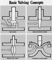
BASIC VALVING CONCEPTS
While it may appear that there are dozens of different mechanical concepts used in the construction of valves today, almost all fall within one of four basic schools of design as far as their primary valving actions are concerned. We have coined some definitions here which, while they are not common industry terms, may serve to help you get the picture of the concepts involved.
PORT CLOSURE: With this type of valve, fluid passes through a specific opening and is controlled by means of a disc or inserted plug in that area. In the case of a disc, sealing off the flow is accomplished by flat positioning against a lip around the opening (seat), whereas plug types involve the insertion of a component into the opening. (Do not confuse the "plug" aspect of these designs with "plug valves." The latter are distinctly different in concept.) Globe, angle, "Y" and needle valves are common examples of port closure designs. Because of the internal configuration of this type of valving, these designs are characterized by a relatively high degree of pressure drop. On the other hand, since water is permitted to discharge uniformly around the circumference of the orifice, port closure designs are well suited for throttling applications. As a general rule, such valves are specified when factors of throttling and frequent operation are involved.
SLIDING OR ROTATING CLOSURE: Unlike the port closure types which involve a specific orifice, these designs control flow by blocking the general passageway through the valve. Such blocking can be accomplished by either sliding a member across the passageway (gate or slide designs), or rotating a member which has a hole through it (plug and ball designs). Causing little or no obstruction in the full "on" position, such designs produce minimal pressure drop (due to their "straight-thru" passageways). With most such valve designs, however, fluid discharge is not evenly distributed when the valve is set in less than the full-on position. As a general rule, these types of valves are best suited for on-off service where throttling is not a requirement.
ROTATING DISC CLOSURE: This concept is somewhat like the sliding or rotating closure designs in that the valving is accomplished in the general passageway rather than in relation to a specific port. The difference in this case, however, is that the blocking of the passageway is accomplished by the rotational positioning of a wafer-like member. Another difference is that the control member, the disc, actually stays in the passageway when fluid is flowing. It is simply positioned end-wise (in line with the flow) in this case, permitting water to flow around both sides. Butterfly valves are the most common example of this approach to valving. There are designs of rotating disc closure that are suitable for both on-off service, as well as throttling (characterized by a minimum of pressure drop).
DIAPHRAGM OR PINCH CLOSURE: In terms of basic concepts, these are among the simplest valve designs. Essentially, the passageway of the valve is blocked by the flexing of a portion of resilient material (usually rubber) across it in some manner. Diaphragm valves accomplish this by deflecting the flexible material down onto a rigid area of the valve body, whereas pinch tube designs involve compressing two walls of tubing together. These designs, too, are suitable for a combination of basic functions, including on-off service and throttling.