In upstate New York, where I live, we are in “heating mode” from late September to early May. Perhaps it’s not surprising that I spend most of my time thinking about hydronic heating applications.
Still, the same physical properties that make water ideal as a conveyor belt for moving heat through a building also apply to its use in cooling.
Chilled water cooling has been used in larger buildings for decades. The chiller in many of these systems may be a large centrifugal machine, or an absorption unit that turns out water in the range of 40º F to 55º F. This water is usually conveyed to air handlers where it passes through a coil to both cool and dehumidify air stream of return air.
I’ve been involved with several residential hydronic cooling projects over the last few years and am pleased with the results. I recommend it as a unique offering that complements what hydronic professionals provide for comfort heating.
Here are some of the benefits associated with small-scale chilled water cooling:
1.A range of products are now available to serve as the chiller. These include:
- Ground-source, reversible water-to-water heat
pumps.
- Air-cooled chillers (e.g. air-to-water heat pumps).
- Small gas-fired absorption cycle chillers that can dissipate heat to
either outdoor air or an earth loop.
- Direct cooling from a lake or large pond in northern climates.
2.It is easier to zone a hydronic cooling system using multiple small air handlers or other terminal units compared to installing multiple motorized dampers in a central duct system. Zoning can be done using zone circulators, or with zone valves in combination with a variable-speed pressure-regulated circulator. The latter option offers the same percentage savings in electrical energy as when used in a zoned heating system. It also eliminates the need for a differential pressure bypass valve in the system. Minimizing circulator power input is even more important in cooling systems because all such power adds to the cooling load.
3. With a properly sized buffer tank it’s possible to size a ground-source or air-source heat pump to the full design heating load of the building and not have it short-cycle during the cooling mode. Such short cycling has been a definite problem in earlier generation water-to-air heat pumps, especially when used in northern climates with relatively low cooling loads. It led to the development of two-speed and most recently, variable-speed compressors. This helps, but at the expense of complexity and higher cost. Using a buffer tank to store chilled water allows a simple and less expensive single-stage chiller to be used. The buffer tank, if properly configured, also can provide hydraulic separation between the chiller-side circulator and the distribution circulator. This is especially important if the latter is operated at variable speeds.
4.Any concern for “frosting” the cooling coil, which can occur with direct expansion coils operating at reduced air flow rates, is eliminated.
5. The potential exists for using a radiant panel to handle the sensible portion of the cooling load and thus reducing the air flow rates to those required for latent cooling (e.g. moisture removal) and ventilation. This hybrid approach significantly lowers the distribution energy required to operate the system. It’s the primary reason underlying increased worldwide interest in radiant cooling.
6.In areas with time-of-use electrical rates, systems can be designed with chilled water storage. Ideally, the chiller would only operate during periods of low electrical rates to drop the tank temperature to where it could absorb the following day’s cooling load. I designed and helped install a residential system using this approach back in 1991. It’s still operating. Adding storage also allows air-cooled chillers to operate at night when both electrical rates and outdoor temperatures are lower. The latter increases both the capacity and the energy efficiency ratio of air-cooled chillers.
7.In applications where there’s a steady demand for domestic hot water, a water-to-water heat pump can serve double duty. The hot side of the heat pump supplies water at temperatures up to 145°F, while the cold side supplies chilled water for cooling. Such applications can nearly double the effective coefficient of performance of a heat pump because both the heated water and chilled water are produced from the same electrical input energy.
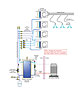
Figure 1.
The hardware
Figure 1shows a small-scale chilled water cooling system using zoned air handlers. Refrigerant lines run from the air-cooled condenser to a flat-plate heat exchanger inside the mechanical room. This heat exchanger is specifically designed to operate as the system’s evaporator with refrigerant gas passing through one side and water through the other. This configuration keeps all water inside the building, and thus eliminates the need to use antifreeze or drain external piping during cold weather.The chilled water produced by the flat-plate heat exchanger routes to an insulated and vapor-sealed buffer tank. Only tanks with foam insulation should be considered for such applications. After the piping is in place, all connections should be sealed with expanding spray foam and wrapped with a vapor-tight jacket. All seams in the tank’s jacket should also be sealed with aluminum foil tape.
A temperature setpoint controller monitors tank temperature and operates the chiller as necessary to maintain it within a certain range, typically from a low of 45°F to a high around 60°F. Chilled water temperatures lower than 45°F are seldom needed and only serve to lower performance of the chiller. Water temperatures above 60°F will compromise the moisture removal capability of the air handler coils.
The flow switch installed between the buffer tank and the heat exchanger is essential. It verifies flow in this loop as a prerequisite to operating the chiller. Without it, the flat-plate heat exchanger could be quickly frozen and damaged should there be a loss of flow.
This distribution side of the system is a home-run layout using zone valves and a variable-speed pressure-regulated circulator. The coolest water in the system also will be the most dense and settle to near the bottom of the buffer tank. Thus, the supply pipe to the distribution system comes out near the bottom of the buffer tank.
I’ve had good results with so-called “hi-velocity” air handlers equipped with higher static pressure blowers to deliver cooling air flow to the building. A typical approach equips each air handler with a discharge trunk duct, to which several 2-in. diameter flexible, pre-insulated “mini ducts” are attached. The latter are easy to route through the framing systems of small buildings and do a good job of sound attenuation. To keep air flow velocities within a good range, plan on seven, 2-in. air outlets per ton (12,000 Btu/hr.) of cooling capacity.
The zone valves are placed on the return side of the air handlers where the water temperature is slightly warmer. This helps minimize condensation, but does not eliminate the need to wrap the zone valve bodies with flexible foam rubber insulation. Don’t wrap the valve’s actuator with insulation, which could cause condensation to form on the internal electrical components.

Figure 2.
Don't sweat it
All piping carrying chilled watermustbe insulatedandvapor-sealed. Omit this detail and condensate damage to drywall surfaces will quickly be evident and lead to costly corrections. I prefer flexible foam rubber insulation with a low vapor permeability. All joints and seams must be closed and glued. This same type of insulation in the form of flexible sheets or tape can be used to encase all portions of valves (other than the handle).The volutes of circulators should also be insulated, but do not wrap the motor can. Chilled water cooling is one application where two-piece or three-piece circulators - as differentiated from wet-rotor circulators - have an advantage. The coupling assembly between the volute and motor helps prevent condensation formation on the latter.
As a rule, don’t install circulators or valves directly above electrical components, or in any area where an occasional drip of condensate would be a problem.
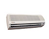
Figure 3.
Terminal unit options
There are several types of air handlers and fan coils available for smaller-scale chilled water cooling.Figure 2shows a small horizontal air handler equipped with a chilled-water coil and condensate drip pan. This air handler supplies cooled and dehumidified air to an insulated plenum that in turn supplies several small-diameter insulated flex ducts. The air handler is located within a conditioned attic space. As such, water can remain in the unit during the winter (assuming the conditioned space remains above freezing). If you need to mount a chilled-water air handler in an unconditioned attic, be sure to make provisions for freeze protection. If you take a close look you will see a secondary drain pan under the air handler. I’m a big believer in these, especially when that air handler is mounted above the ceiling in a multimillion-dollar house.
Figure 3shows an example of a small fan coil designed for high wall mounting. This unit is equipped with an internal condensate drip pan, and thus suitable for chilled water cooling. In most applications, 3/4-in. piping to and from this type of fan coil is sufficient. Although it could be rigid pipe, I prefer to specify flexible PEX tubing for these applications. Multiple fan coils can be supplied from a central manifold station using a home-run distribution system. Be sure to include 3/4-in. piping to route condensate from the drip pan to a suitable drain.

Figure 4.
Looking up to the future
Radiant ceiling, wall or floor panels also can be used with chilled water cooling, but only in combination with a reliable dew-point controller that ensures surface temperature remains above the dew-point temperature of the room by at least 2°F or 3°F at all times.Given the growing interest in radiant cooling, as well as the established comfort of radiant panel heating, I think radiant ceilings are best poised as one of the most versatile hydronic terminal units (for heating and cooling).
Figure 4shows the construction details for a radiant ceiling system I’ve developed and used over the last decade.Figure 5shows this system during installation.
This construction uses common 6-in. by 24-in. aluminum heat transfer plates along with 1/2-in. PEX-AL-PEX tubing spaced 8 in. apart. 3/4-in. by 7 1/4-in. strips of foam-faced polyisocyanurate insulation board support the plates and tubing as shown in the above figures. The foam strips and aluminum plates are held in place using standard contact cement. Notice the 2 1/2-in.-long drywall screws are easily placed halfway between the tubes so they do not have to penetrate the aluminum plates.
This construction results in a low-mass panel that can respond quickly to changing internal load conditions. When finished, this ceiling is indistinguishable from a standard drywall surface. This panel also will provide excellent performance if used for radiant ceiling heating during winter.

Sucking it up
The ability of a chilled surface to absorb heat from room air as well as from warmer objects in the room is called sensible cooling capacity. The word sensible implies no condensation of water vapor occurs on the panel.Formula 1(below) can be used to estimate the sensible cooling capacity of a cooled ceiling based on its average surface temperature.

Qabsorbed = rate of sensible heat absorption by the cooled ceiling (Btu/hr/ft2);
Troom = room air temperature (°F);
Tceiling = average surface temperature of ceiling (°F); and
1.1 = an exponent.
Thus, a ceiling with an average surface temperature of 65°F operating in a room where the air temperature is 75° F would have the following rate of heat absorption:
The sensible cooling capacity for a radiant ceiling, wall or floor is always constrained by the current dew point of the room’s air. Chilled water temperatures must be controlled so the surface of the ceiling remains 2°F to 3°F above the current room dew point.
The design cooling load of a typical house is usually in the range of 12 to 18 Btu/hr./ft2. This total load consists of both sensible cooling (lowering the air’s temperature) and latent cooling (removing moisture from the air). Depending on climate, anywhere from 65% to 90% of the total load will be sensible cooling. These numbers, in combination with the performance estimate for the radiant ceiling given by the previous formula, indicate radiant ceiling cooling can handle a significant portion of the total load, especially in drier climates.

Figure 5.
Wringing out the water
Sensible cooling without latent cooling will generally not produce comfortable indoor conditions. Thus, nearly all radiant cooling systems require a means of moisture removal. One of the most common approaches is to use a chilled water coil in an air handler designed with a drip pan.Figure 6shows a possible way to set up a small chilled water cooling system that combines a radiant panel with a chilled water air handler.
Chilled water is produced by a geothermal water-to-water heat pump, which maintains the buffer tank temperature between some preset upper and lower limit whenever there is a demand for cooling. The coolest water is extracted from near the bottom of the buffer tank.
The first load on the chilled water loop is the air handler, through which passes a combination of re-circulated air and outside ventilation air. A mixing damper controls the proportions of each. The mixed air passes over the chilled water coil for moisture removal and passes on to the occupied spaces. Flow through the chilled water coil is induced by the differential pressure across the partially closed globe valve (V1) whenever circulator (P1) is operating.
The second load on the chilled water loop is the radiant cooling panel(s). The three-way motorized mixing valve is operated by the dew-point control, which continually senses room conditions and modulates the valve to keep the supply water temperature 2° or 3° above dew point.
The system shown inFigure 5is for dedicated cooling. However, with some minor variations it could also provide radiant panel heating.
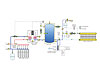
Figure 6.
Develop an offering
One of the common questions that often follows a discussion on hydronic heating between a potential customer and supplier is: What should I do about cooling? Given the options we’ve just discussed your response could be: “Let me tell you about hydronic cooling…”Develop a hardware solution that’s ready to go and you may find a whole new way to profit from modern hydronics technology.