
The H1N1 virus has captured a lot of attention recently. It’s a tough bug that spreads quickly and marginalizes what it infects, sometimes to the point of total failure. The health industry’s obvious goal is to minimize its spread and eventually eradicate the virus.
The North American hydronics industry has its own viruses. When least expected they can spring up to marginalize thousands of dollars’ worth of hydronic system components and installation labor. There’s one “bug” that I’ve been watching for several years. I’ve named it P1/S1. It’s a piping detail that’s unique to North America (apparently the Europeans figured out how to avoid it a long time ago).
P1/S1 crosses my path in the form of numerous S.O.S. calls and e-mails to our office. Given the frequency at which these reported infections occur, it’s high time to discuss how to deal with P1/S1. Fortunately, this virus responds to proper treatment every time. If all North American hydronic practitioners would just follow this treatment, P1/S1 could quickly be eradicated.
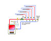
Figure 1a.
Old Habits Die Hard
Prior to the resurgence of interest in primary/secondary piping, most residential and light commercial hydronic systems used piping headers at the boiler as the beginning and ending points for branch circuits. For years the concept was simply to pipe the zone circuits across the headers.This concept also applies to traditional “2-pipe” distribution systems. When zone valves are used, a central circulator creates a pressure differential between the hot water supply and return mains. This pressure differential pushes flow through any open piping path connected from the supply to the return mains. Adding a branch circuit is simply a matter of connecting “across the headers.” The concept is shown inFigure 1a.
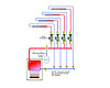
Figure 1b.
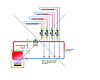
Figure 2.
Please Don't Do This
Both traditional 2-pipe and primary/secondary piping have worked well in the past, and certainly can continue to work well when properly applied in future systems. However,things go south in a hurry when the concept of connecting across the headers is stirred in while attempting to cook up a primary/secondary (P/S) system.The resulting assembly is neither “2-pipe” nor primary/secondary. Instead, the undefined piping aberration becomes the battleground for a war between competing circulators. The water flows in various parts of the system become the refugees in this war. The compromised comfort becomes the collateral damage.Figure 2shows an example of this piping aberration.
My take on why this “infection” occurs is as follows: It appears the installer’sintentwas to create a primary/secondary system. At least that’s the way he starts out. However, once he gets to the piping downstream of the primary circulator, he attaches the supposed “secondary circuits”across the headersrather than to pairs of closely-spaced tees, as would be required for proper primary/secondary piping.
Perhaps the installer was so used to connecting branch loads across the mains in older 2-pipe systems that he momentarily forgot about how primary/secondary systems work at the decisive moment when tees meet tubing. Sudden impulses to change what you are about to do occur frequently when you operate in the “design-as-you-solder” mode.
The piping shown in Figure 2 creates a significant pressure differential on the zone circuits whenever the primary circulator is running. The “primary circulator” in such a system is usually wired to operate when any of the load circuits are on. The pressure differential created by flow along the main piping is only exasperated by a partially closed ball valve at the right side of the “primary loop.” The presence of this valve has always baffled me. I don’t see any legitimate purpose for it. Yet it seems to be a consistent characteristic of a P1/S1 infection.
The check valves in the load circuits can only “hold back” about 0.3 psi. The pressure differential created by the “primary circulator” and piping loop will often be many times higher. The result - you guessed it - is overheating due to “ghost flow” in nearly all zones.
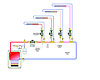
Figure 3.
I Sorta Kinda Think It's Primary/Secondary Piping
There’s no need to be uncertain as to whether or not you have designed and/or installed a P/S system.If you don’t have closely spaced tees, you don’t have a primary/secondary connection between intersecting piping loops.Without this connection, the circulators will interact to an extent determined by the pressure drop between the supply and return tees. In an extensive piping system with many circulators, flows in various parts of the system will change every time a given circulator turns on or off. It’s anybody’s guess what happens to flows in various parts of the system as the circulators duke it out.If your intent is to make a series primary/secondary system, the correct piping layout is shown inFigure 3
Each secondary circuit is connected to the primary loop with a pair of closely spaced tees. There should be a minimum of six pipe diameters of straight pipe upstream of any pair of tees. There should also be a purging valve near the end of each secondary circuit - just before it connects to the return tee. The secondary circuits can be spread out along the primary loop. They don’t necessarily all have to be on the “top” of the loop as shown in Figure 3.
The piping shown in Figure 3 allows all circulators to “get along,” but it creates another less-than-ideal situation. There will be a temperature drop along the primary loop each time flow passes an operating secondary circuit. The magnitude of this drop is determined by the rate of heat transfer to the secondary circuit, and the flow rate in the primary loop. Will it be a problem? Not necessarily, IF the designer compensates by upsizing the heat emitters in the downstream secondary circuits to allow for the temperature drop. Unfortunately, few designers do this.
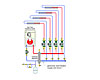
Figure 4.
Better Options
Although series primary/secondary piping has been widely used in residential and commercial systems, there are piping methods that simplify the assembly and eliminate the sequential temperature drop between secondary circuits. One example is shown inFigure 4.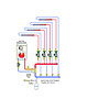
Figure 5.
The system inFigure 5is a slight variation on Figure 4. It uses a single set of closely spaced tees and the generously sized headers to create the same effect. A high-performance air separator is added to provide the air removal function since the hydraulic separator is not present.
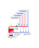
Figure 6.
So if your goal is to create primary/secondary piping, don’t infect the system with P1/S1 by connecting the load circuits “across the headers.” However, if your goal is to create simple and efficient zone circuits without strict allegiance to a specifically named piping method, I suggest one of the approaches shown in Figures 4-6. In the end, few people will care what you call the piping provided it delivers comfort and reliability.