Figure 1.
Late last year I was asked to write columns on hydronic heating forSupply House Times. I hesitated at first. Not because of lack of experience with hydronics - I’ve been designing, writing and teaching about hydronic heating systems for 30 years. But I’ve done this from the perspective of an engineer, rather than someone directly involved with the distribution and sale of hardware used in hydronic systems. What could I bring to the table that would be of interest to distributors and wholesalers?
I pondered this for quite a while, and consistently came back to a fundamental question: What value do distributors of hydronic hardware bring to the market?
In today’s market, installers can find almost any hardware they need without venturing beyondebay.com. Commodities like pipe, fittings, electrical hardware, circulators, controls, and baseboard are readily available from the “big box” stores at prices few traditional distributors can compete against.
Based on this, it seems obvious that distributors must deliver value, beyond that associated with the lowest price, in order to retain current accounts and grow their local market. Much of this value must come in the form of product knowledge, design assistance and field support. These days, it’s not enough to simply function as an “order taker.”
Without distributors who consistently keep local installers up-to-date on products and design methods, local implementation of hydronic heating gets stuck in a rut. The same mistakes get repeated, and the industry does little more than attempt to hang on to its currently small market share.
During my tenure in the industry I’ve been convinced that distributors have a tremendous influence on system design and hardware selection. This is especially true with residential and light commercial projects that are often - and I really don’t like this term - “non-engineered.” What the local distributor recommends is usually what gets installed. Right or wrong, modern or antiquated, it happens every day.
So as I see it, distributors who expect to thrive in the hydronic heating marketplace must acquire and disseminate information that lets local installers take advantage of the most up-to-date technology. To that end, I will use this and future columns to discuss new design and hardware concepts that will shape the future of North American hydronics.
Five for Now
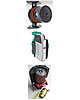
So let’s start off with a discussion of five trends in North American hydronic heating. These trends involve hardware that manySupply House Timesreaders will likely deal with in 2009 and beyond.1. Smart, Variable-Speed Circulators:One of the biggest advances in hydronic heating technology over the last 20 years has occurred only recently. It’s the development of “smart circulators.” These devices use electronically commuted (ECM-) motors and microprocessor controllers to regulate the circulator’s speed based on the instantaneous needs of the distribution system. When zone valves open, the circulator automatically speeds up and vice versa. Some examples of variable speed circulators sized for residential and light commercial applications are shown inFigure 1.All of these products were developed in Europe, but are now available in North America.
Why should distributors care about these new devices, when they already sell plenty of standard wet rotor circulators?
For starters, ECM-based smart circulators are almost twice as efficient at converting electrical energy into head energy relative to standard circulators. Stated another way: They produce the same flow in a given system using about half the wattage of a current generation circulator.
Imagine you could offer contractors a boiler that uses half the fuel of other currently available boilers. I’m sure most of you would immediately question the validity of such a performance claim, and justly so. Perhaps you’ve followed the incremental improvements in boiler efficiency over the years and know that even gains of 2% or 3% are considered significant.
Well, it’s finally time for the lowly circulator to make a “quantum leap” in performance. 2009 will be a significant transition year for these new circulators in North America. Three manufacturers now offer these products in this market, and it’s likely other manufacturers will soon follow. One has only to look at how the market for residential modulating/condensing boilers developed over the last five years to see a similar trend taking shape for these new circulators.
Initially these circulators will appeal to installers looking to “greenify” their systems. They are, without question, the most efficient devices available for moving heat from a mechanical room to the heat emitters. Other installers will keep an eye on these “early adopters,” and word will soon spread that these products deliver on their promised performance. From that point, they will gain market share quickly, and eventually become the standard rather than the exception. The latter will take time, probably several years, but it’s inevitable this is the direction the market is headed.
If higher initial cost is an issue - and it always is - remember that these circulators automatically regulate differential pressure, and thus eliminate the need for a differential pressure bypass valve. The savings from not installing this valve significantly reduces their “net” higher first cost. Combine this with electrical energy savings of at least 60% relative to current generation circulators and the result is payback that’s likely under five years. How many solar thermal systems, wind turbines, and other more visible implementations of “green energy” can make such a claim?

Figure 2.
An example of a parallel primary/secondary system is shown inFigure 2.This configuration ensures that each secondary circuit is supplied with water at the same temperature. The closely spaced tees ensure there will be no hydraulic interference between the circulators.
Suppose you could attain the same benefits offered by this system, but with simpler piping and no need for a primary loop circulator? This is possible, and the details are shown inFigure 3.
The vertical flow velocity within a hydraulic separator is very low. This minimizes pressure drop between the top and bottom connections - essentially the same as using a pair of closely spaced tees to connect a secondary circuit to a primary loop. When the hydraulic separator is fitted with a set of short and generously sized headers, there is virtually no interference between simultaneously operating circulators.
The hydraulic separator reduces the circulator power required by the system without sacrificing any of the benefits offered by primary/secondary piping. It also serves as a central air and dirt separator for the system, eliminating the need to install other hardware for these functions.
Several companies now offer hydraulic separators in North America. These devices are sure to capture an increasing percentage of the market as distributors learn their fundamental simplicity.
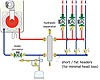
Figure 3.
This is not a state-of-the-art solution. In Europe it’s been replaced by the concept of a central boiler plant with equipment that accurately meters the amount of thermal energy sent to each unit in the building. Such metering involves continuous measurement of the flow rate and temperature differential of the flow stream sent to each unit.
Each tenant or owner is billed based on the heat delivered to his or her unit. Get ready to see this concept move quickly into the North American market.
A conceptual diagram for a typical system using heat metering is shown inFigure 4. Each space in the building is equipped with its own substation, which provides space heating and domestic hot water using heat supplied from the riser piping.
BTU metering saves energy because it capitalizes on the greater efficiency of a staged and modulated boiler plant relative to the part load efficiency of small boilers or water heaters. Everyone supplied by the system benefits from these savings.
This approach also reduces both installation and operating cost by eliminating the basic service charges associated with having a separate gas meter for each unit.
In some cases BTU metering also eliminates the need for fuel supply piping and venting from each space within the building.
Finally, BTU metering encourages energy savings. Studies have shown reductions on the order of 30% relative to systems that don’t link utility charges directly to usage.
Hardware for BTU metering, even “Web-enabled” BTU metering, is already available in North America, and more is likely to enter the market in 2009. Are you ready to advise customers on the benefits of BTU metering and show them how it’s implemented?
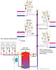
Figure 4.
An emerging trend is use of PEX and PEX-AL-PEX tubing along with these same manifolds to supply other types of heat emitters such as fin-tube baseboard, panel radiators and small air handlers. This approach is often called a homerun distribution system.
Homerun systems are especially helpful in retrofit applications. The small diameter flexible PEX or PEX-AL-PEX tubing is much easier to snake through closed framing cavities compared to rigid pipe. Homerun systems also provide the same water temperature to each heat emitter, and thus eliminate the sequential drop in supply water temperature associated with series loops or 1-pipe distribution systems. They also allow the flow through each heat emitter to be adjusted to help balance system heat output. Finally, homerun systems generate less flow resistance than do series loops or 1-pipe systems. This reduces pumping power without affecting comfort. Given these benefits and the availability of modern materials to implement them, the use of rigid copper for an entire distribution system will be declining.

Figure 5.
This system brings together many of the previously discussed details: homerun distribution piping, valve-based zoning, and a variable speed ECM-based circulator. It provides high thermal efficiency as well as high hydraulic efficiency, and offers simplicity that belies its sophistication.
Hopefully these trends will whet your appetite to dig deeper and motivate you to keep your distribution business on the cutting edge of hydronics technology through 2009 and beyond.