To best understand what we're dealing with in this month's section, it's a good idea to have read the preceding one, which laid some rather important groundwork. Our coverage here will begin a two-month look at specific examples of valve design in the category of products we have termed "general application" types. We'll give you a description of the valving concept in each case, explain the service applications for which it is best suited, and examine the variations of construction.
While this information will not cover every conceivable valve made, it will hit the majority of those comprising the most active portion of the valve market today.
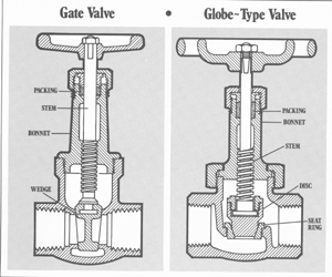
GATE VALVES
Gate valves are the most common example of the valving concept we described as "sliding or rotating closure" in the previous section. To make this definition a bit more precise, gate valves utilize a sliding closure. In such designs, a control member slides across a general passageway in order to control fluid flow (like a sliding gate - hence, the name). One of the most significant characteristics of this type of valving is its straight-through, unobstructed passageway when set in the "full on" position. This is made possible by the control member lifting entirely out of the path of flow. As a result, gate valves are characterized by a minimum of turbulence and pressure drop in operation.
While gate valves are good for applications requiring these two factors, they are not recommended for installations in which throttling would be a function. Set in a partially open position, the key valving components have a tendency to erode quickly due to the high velocity fluid passing through a narrowly restricted area. In addition, such use of a gate valve typically results in objectionably noisy operation. Beyond these problems, throttling with gate valves is not recommended simply because this type of design doesn't do a very good job in performing that function. Since the greatest percentage of flow modulation occurs with the initial opening movement of the control member, there is a poor control ratio between flow rate and stem rotation. In other words, gate valves are designed for service requiring them to be either fully on or fully off - but not in between (throttled). As a rule, gate valves are not used when there is a requirement for frequent activation, since the valving design is relatively susceptible to wear.
Construction: The key components in a gate valve are the wedge (control member) and the seats. Unlike some types of valve design, there are actually two seat surfaces in this case, between which the control member is "wedged" for closure. The seat aspect of a gate valve is designed as an integral part of the basic valve body in some cases, and as a separate replaceable part in others. In cases where frequent maintenance is a concern, this latter type would be specified.
There are four common approaches to the design of the wedge itself:
1) The simplest is the solid wedge, a one-piece rigid design suitable for general applications.
2) The flexible wedge is also a one-piece design, but has a configuration that permits a degree of flexing, to more precisely conform to the seat surfaces. Flexible wedges also compensate for thermal expansion and contraction conditions, while still retaining the capability to open easily.
3) The split wedge design is another type that allows a precise mating with the respective seals. In fact, one half can often seal even though foreign matter prevents the other from full closure. Here again, this type of wedge design is able to compensate for thermal changes. Without this independent alignment of the two halves, there would be a tendency for binding of the wedge when a valve is shut off in a hot condition and later cools. With this design, wedging pressure is relieved before the wedge is lifted upward, thus reducing friction and wear.
4) The final type of gate valve control member we'll cover here is called a double disc design rather than a wedge. In this case, the control member mates between the two seats in a parallel fashion, with no angle to the seat surfaces. As this type of design approaches the closure position, the two halves are spread against their respective seats by a component inside. Like the flexible and split types, the double disc wedge is able to self align in relation to each of the two seats.
THE GLOBE FAMILY
This next category of valve design actually includes four different sub-categories - the globe valve itself, the angle valve, the "Y" valve, and the needle valve. All utilize the "port closure" concept of valving. By this, we mean that fluid passes through a specific opening (rather than a general passageway, as in the case of gate valves), and the fluid is controlled by means of a stem-mounted disc or inserted plug in that area.
While lacking the straight through, unobstructed passageway of the gate valve, these globe types are superior in two key respects - throttling and serviceability under frequent use. They are better at the throttling function because they permit fluid to exit uniformly around the circumference of a seat, rather than "slicing" down to limit passage through a narrowly restricted area. Of the four specific valve types included in this "family" category, the first three utilize essentially the same basic mechanics laid out in different ways. Since the classic in-line globe valve causes the fluid to travel the most devious route, it has the greatest degree of pressure drop of the group. The angle valve causes fluid to take a simple 90? bend, which results in less pressure drop, but is somewhat limited in application in that it does not provide straight in-line connections (shaped like a 90? elbow in that respect). The "Y" valve provides the straightest passageway of the three by positioning the port closure on an angle across the passageway. While superior to globe and angle valves in terms of turbulence and pressure drop, "Y" valves still do not match the gate valve design from the standpoint of a straight, unobstructed passageway.
Needle valves are essentially a specialized type of globe valve designed to provide a very precise throttling control. This is accomplished by means of the configuration of the tapered needle plug that mates with the inside of the seat, and the use of extremely fine threads on the stem to assure gradual travel. Like conventional globe valves, the needle variety is characterized by a high degree of pressure drop.
Construction: There are two primary components in the valving mechanisms within the globe family - the seat (seat ring) and the disc (control member). As in the case of gate valves, seats are provided as either integral or as separate replaceable components (called "renewable"). Each specific seat design is made to conform to the type of disc with which it is mated. The discs take a variety of shapes based on the function involved, falling into three main categories:
1) A composition disc is flat and mates with the top surface of a seat for sealing. This type can be made of a variety of nonmetals, most commonly involving various rubber compounds.
2) Metal discs are designed to mate just inside the opening of a seat having a tapered or radiused (rounded) profile. This design provides good sealing characteristics in applications in which a composition disc would not be adequate to handle the temperature or nature of the fluid involved.
3) Plug discs are metal, too, the difference here being their configurations and means of sealing. These are somewhat like longer versions of the metal disc designs, and again, seal against the inside surface of the seat opening. There are a variety of specific designs in this category. In general, plug-type globe valves provide superior throttling characteristics to the composition and metal discs, and are more resistant to wire draw erosion. (This type should not be confused with plug valves, which involve an entirely different valving concept and basic construction.)
Next month: A look at other common valve designs, including plug, ball butterfly, and diaphragm types.